You probebly really don't want to be here - this may well contain several hundred pics by the time I am done.
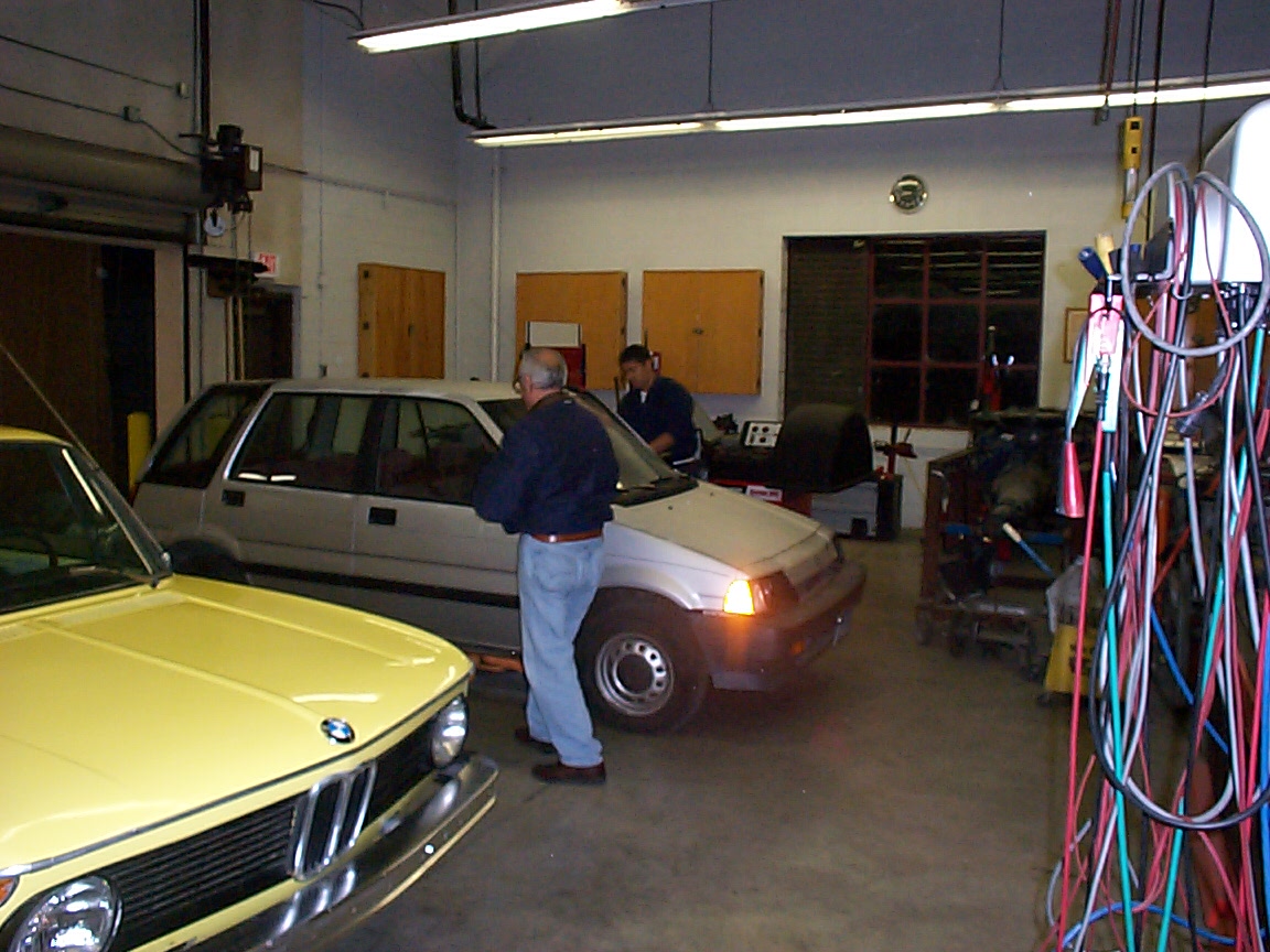
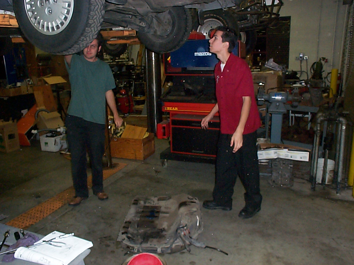
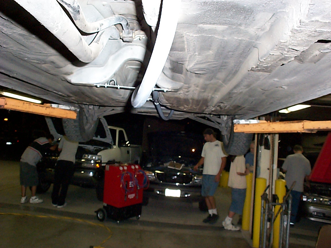
As a note, these are not my shop facilities - I am taking a class in alternate propulsion from Prof. McFarland at Saddleback Community College.
This is my picture working directory, where I save pictures to help me understand the project.
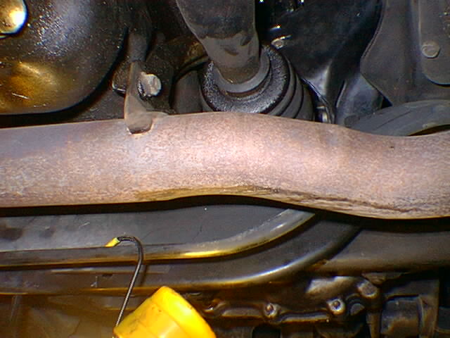
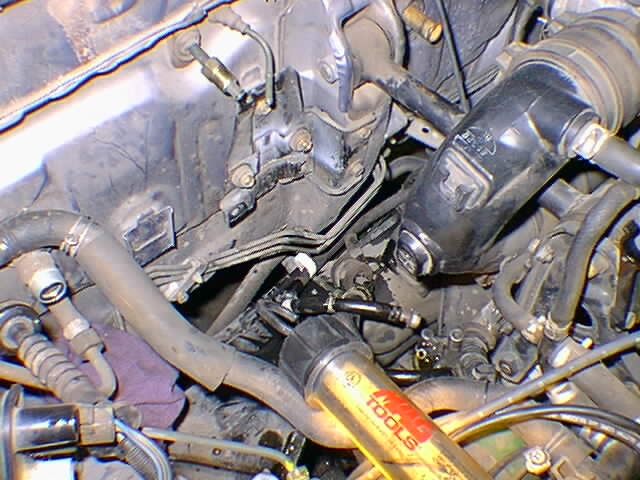
this is another view of the CV joint, from the passenger's side
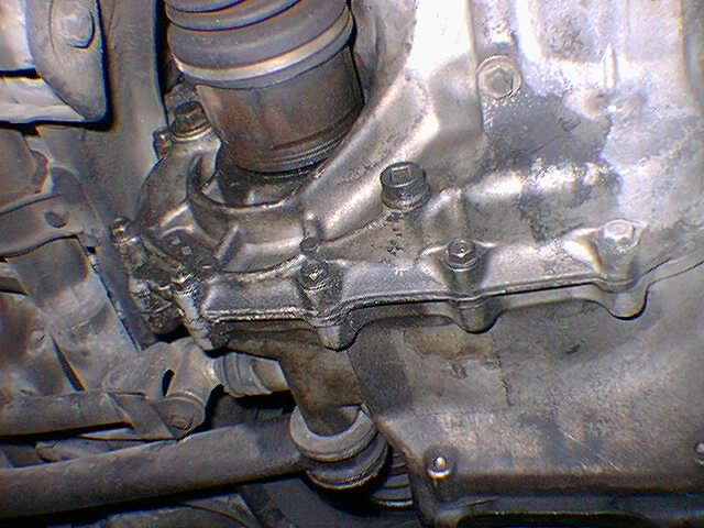
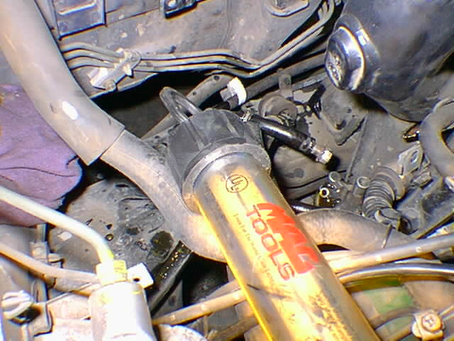
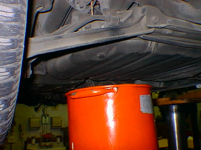
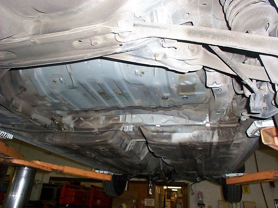
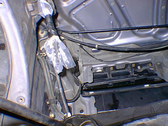
this is a picture of the inner CV from the driver's side. That's the oil pan you see next to it, and the exhaust pipe under it
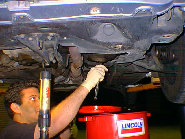
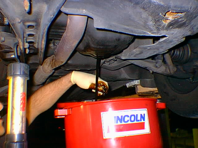
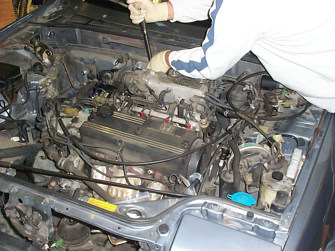
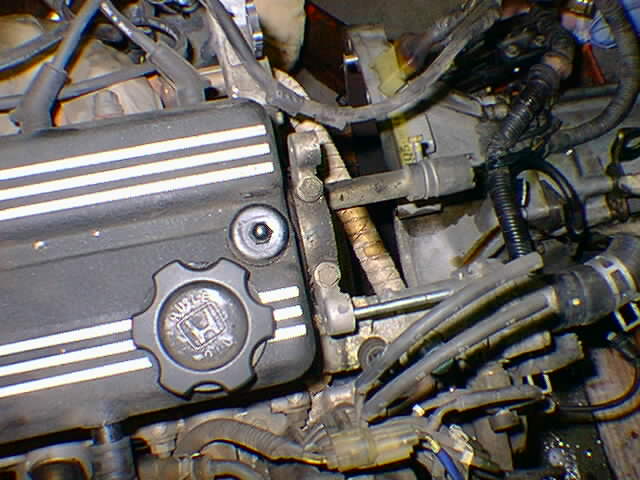
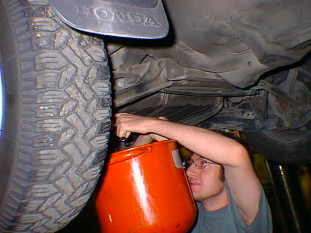
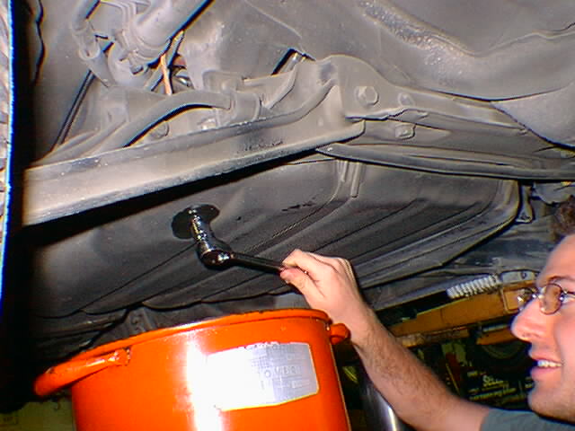
the ceremonial turning of the first bolt - to drain the oil from the engine. We also drained the transmission fluid and the coolant. Still to go are the power steering fluid and the A/C system
Unfortunately I have no pictures of us removing the exhaust system, but remove it we did.
The bolt was stripped. Good thing I'm converting this car ;-)
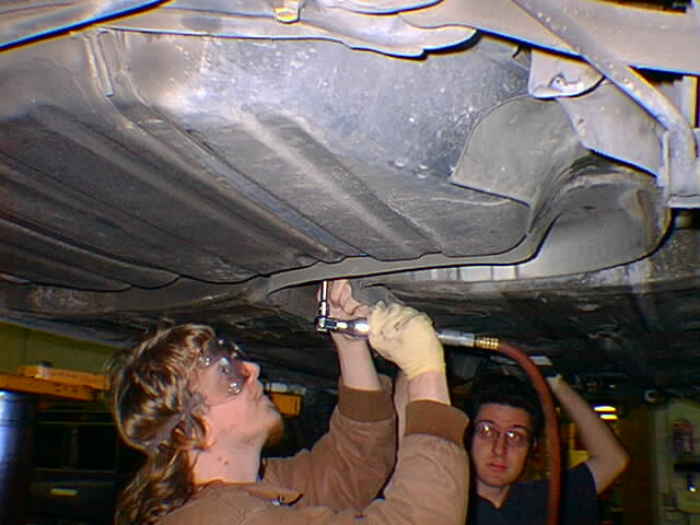
this is me, removing the heat sheild for the exhaust system/
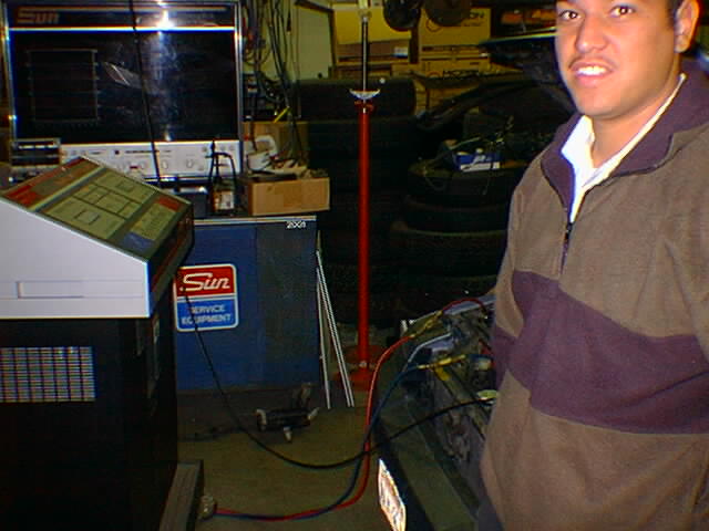
this is Miguel, watching the 'fang' suck all the refrigerant out of the car's A/C system. Chances are, if you go to your local communitiy college and beg, they'll be glad to do the suck for the value of the refrigerant and a small donation. But I didn't say that.
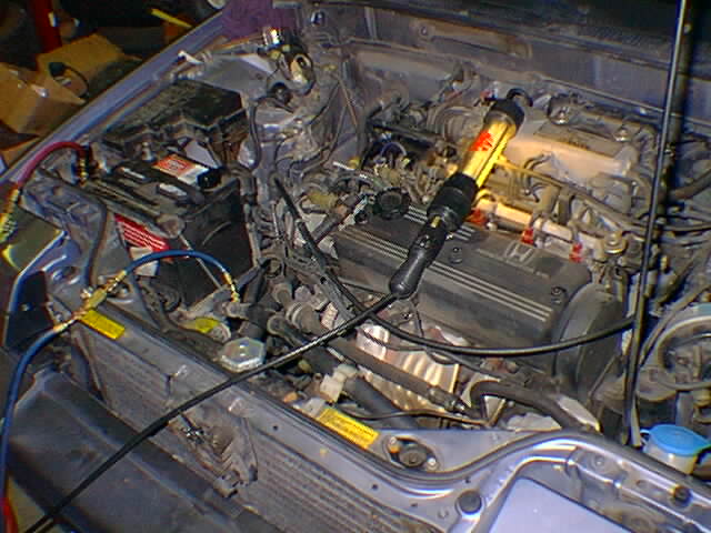
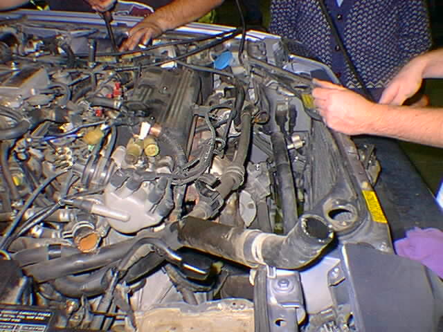
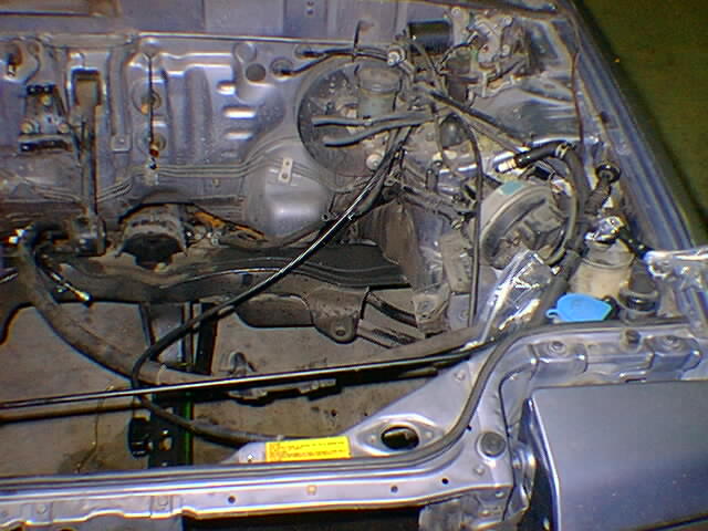
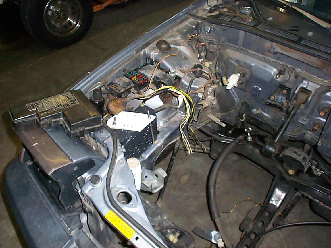
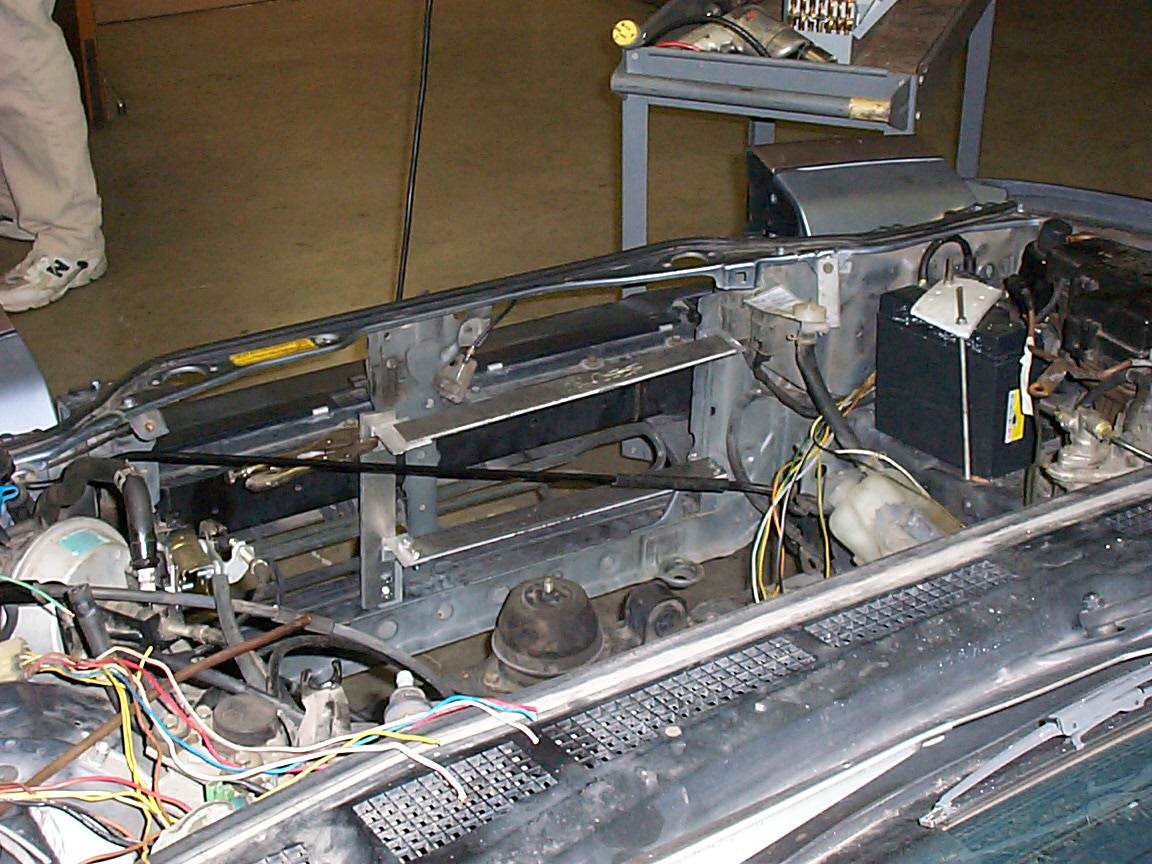
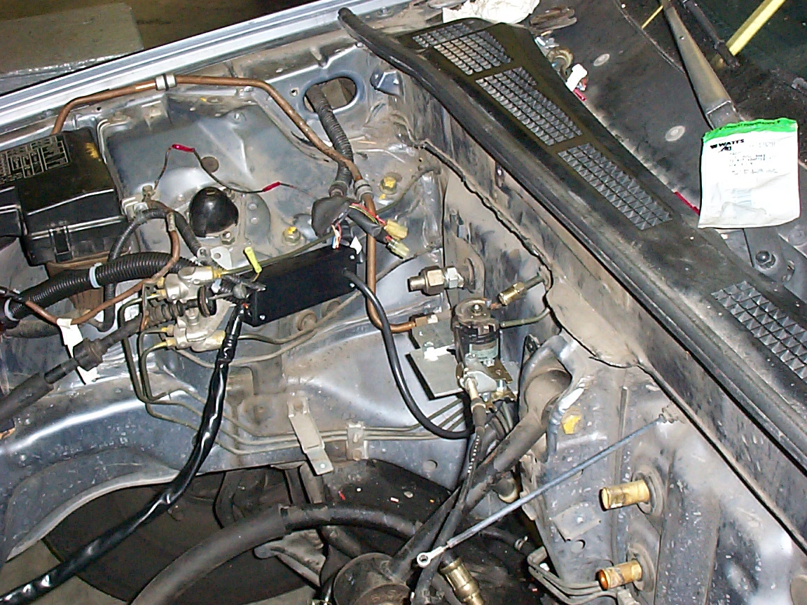
this is the engine compartment with the air shroud and vacuum control unit removed
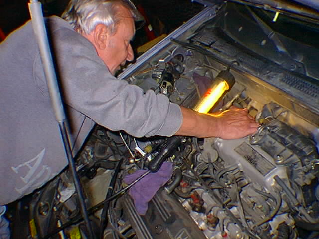
this is Leo, helping remove the fuel filter
this is the fuel filter that didn't want to come off - and we mean it _really_ didn't want to come off.
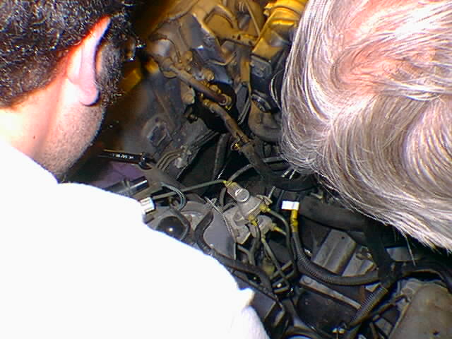
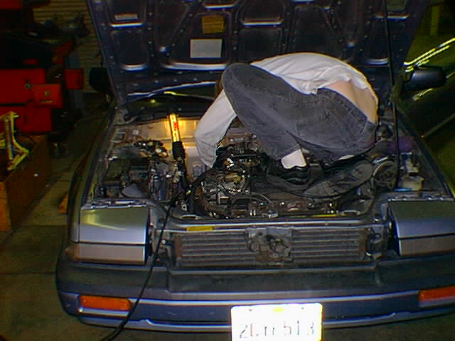
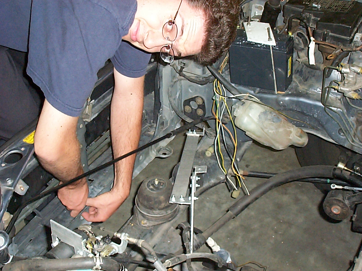
this is me, perched on the engine, cutting the heater core lines prior to removing them.
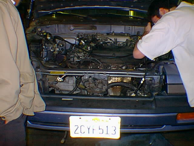
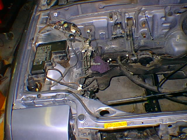
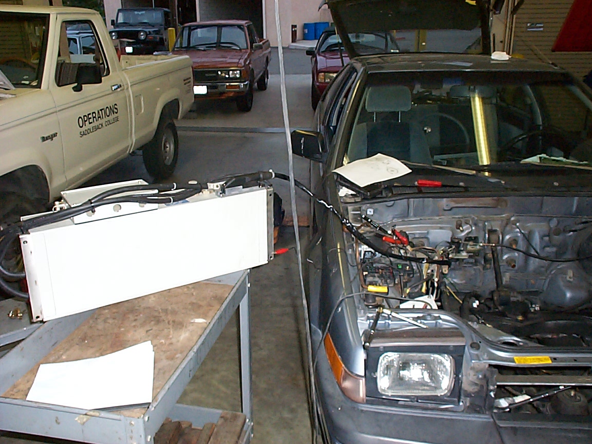
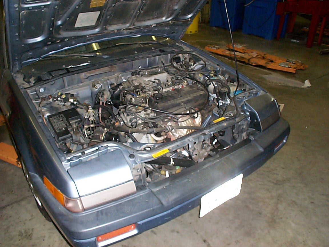
this is a picture of my engine compartment, as we were removing the radiator
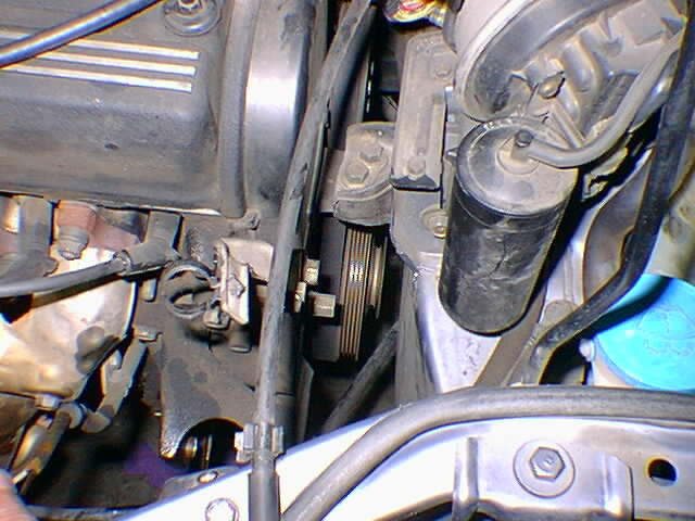
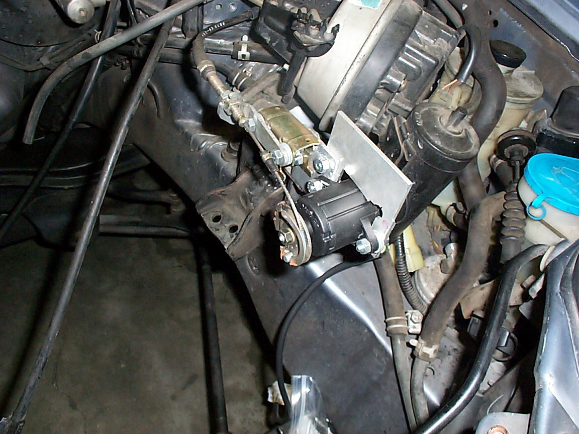
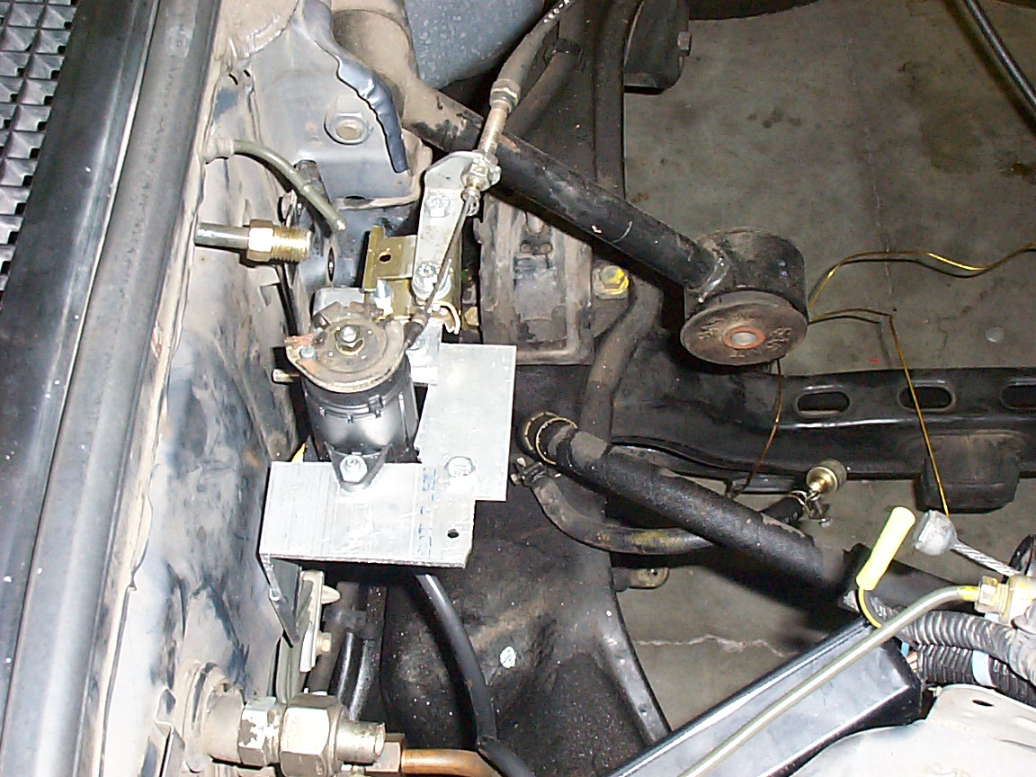
this is a closeup of the old power steering pump, prior to removal. We plugged up one of the lines with a old spark plug, and the other with a bag and some electrical tape
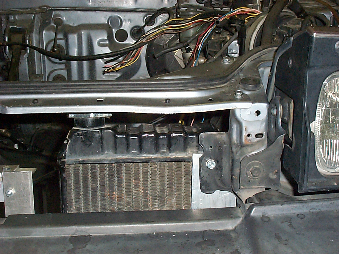
this is the front of the car, sans radiator, as Josh ('breaker-bar-boy') shows his stuff removing a bolt from the AC compressor.
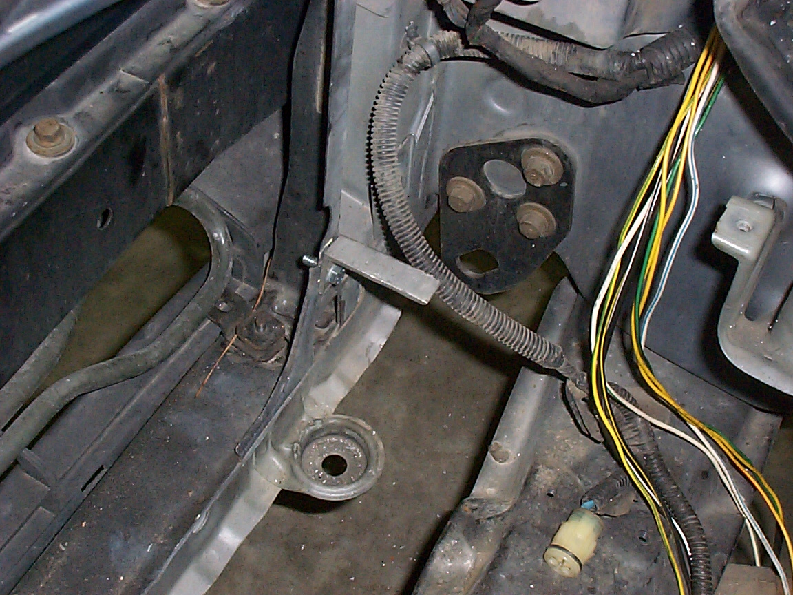
this is the spot where the power steering pump was. No more P/s pump
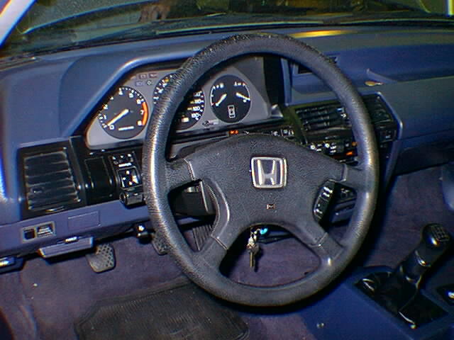
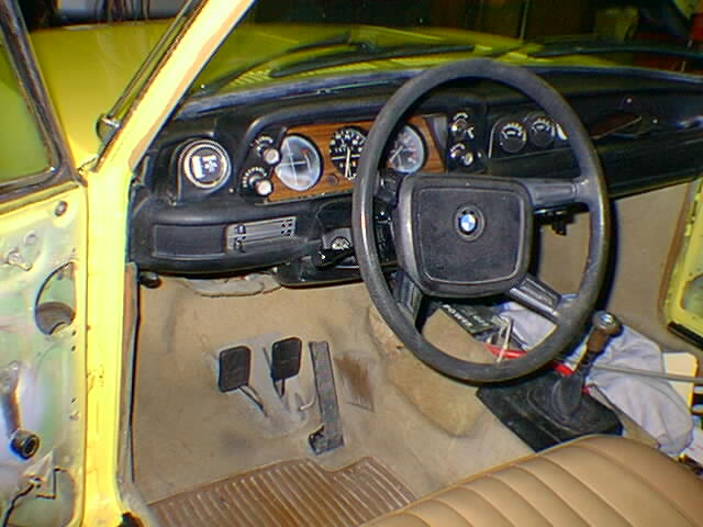
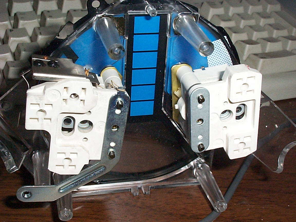
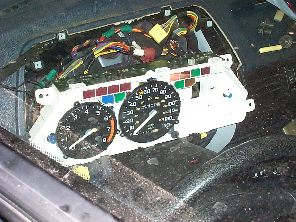
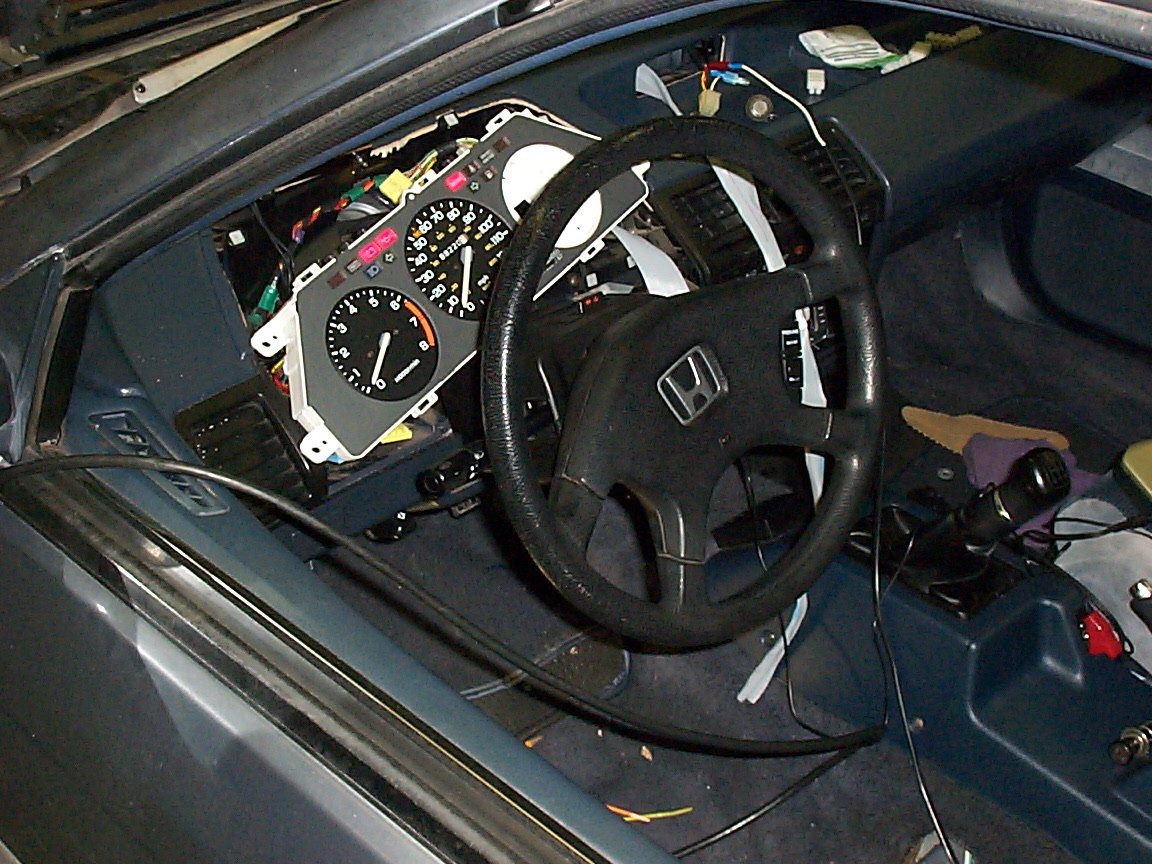
this is the user interface of the car, pre modification
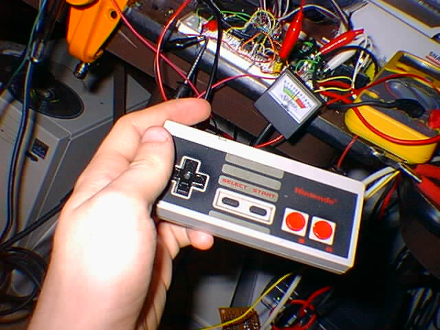
this is me controlling a analog metter with a nintendo controllor, completing the test of the UI components
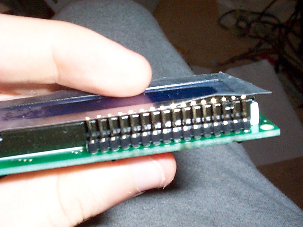
this is me controlling a analog metter with a nintendo controllor, completing the test of the UI components (see, the needle moves) this is me controlling a analog metter with a nintendo controllor, completing the test of the UI components (and wow, I can precisely position it.. resolution of about 5000 steps full scale this is a high res pic of the UI LCD module with cablethis is a high res pic of the UI LCD module without cable
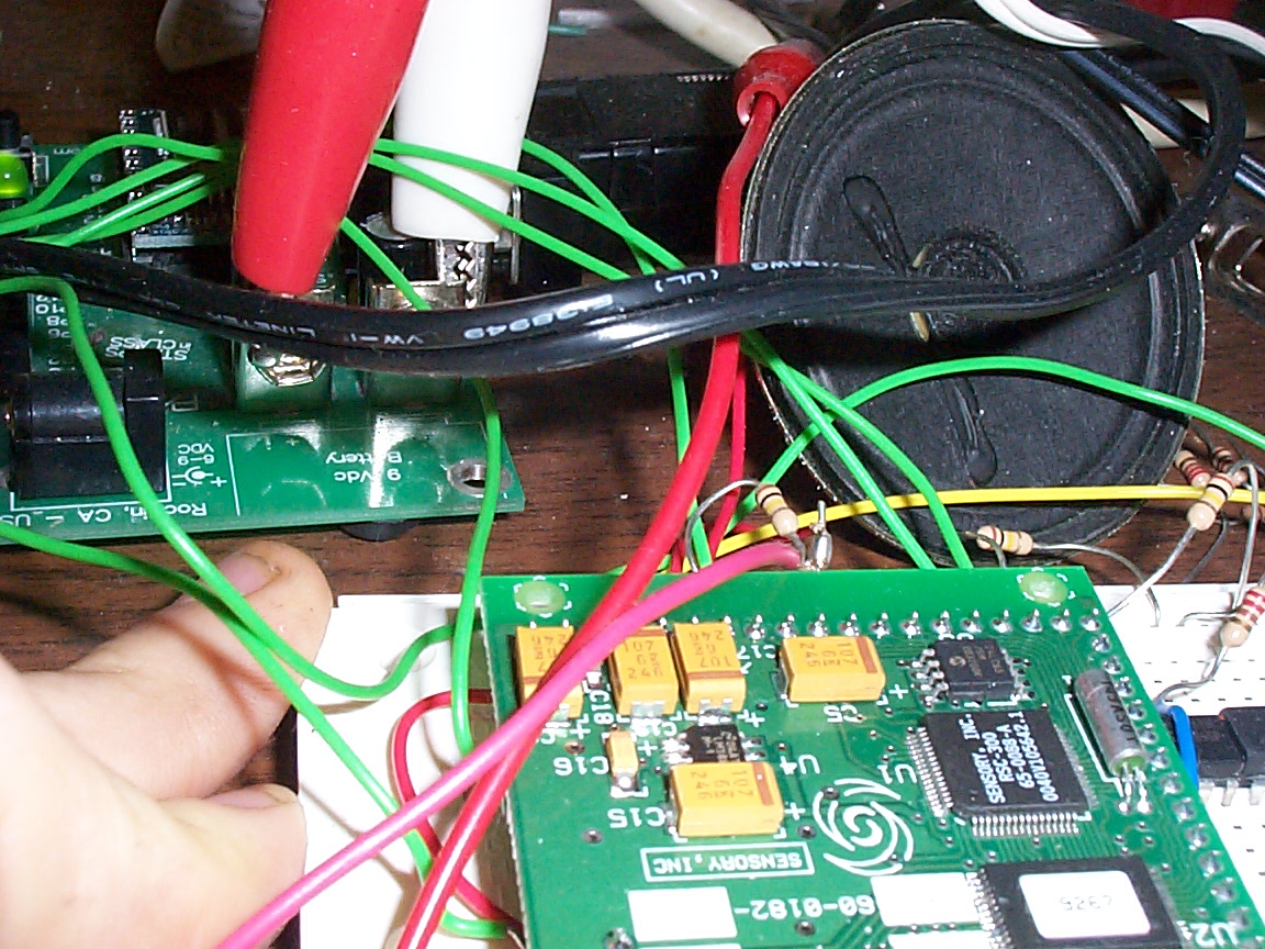
this is a high res pic of the hardware voice recognition module being tested.
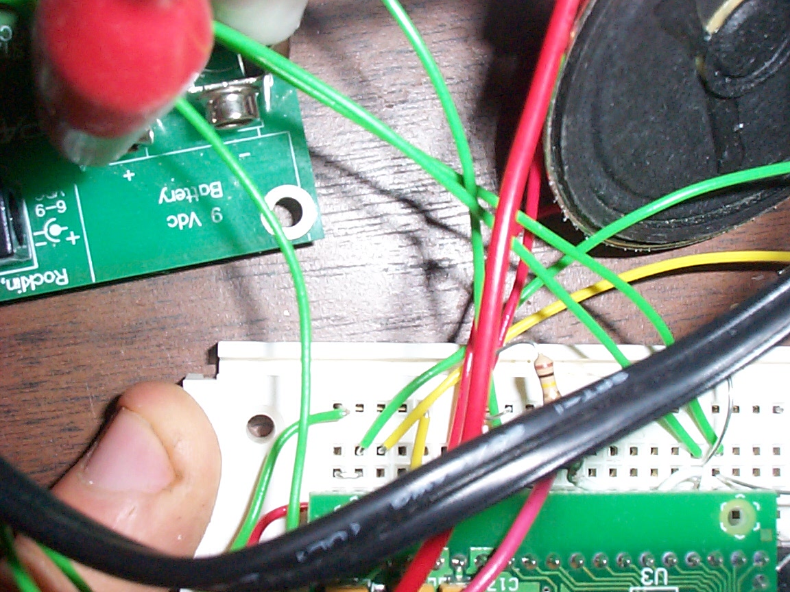
this is another high res pic to capture which input busses were connected.
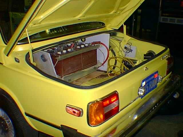
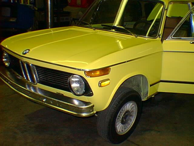
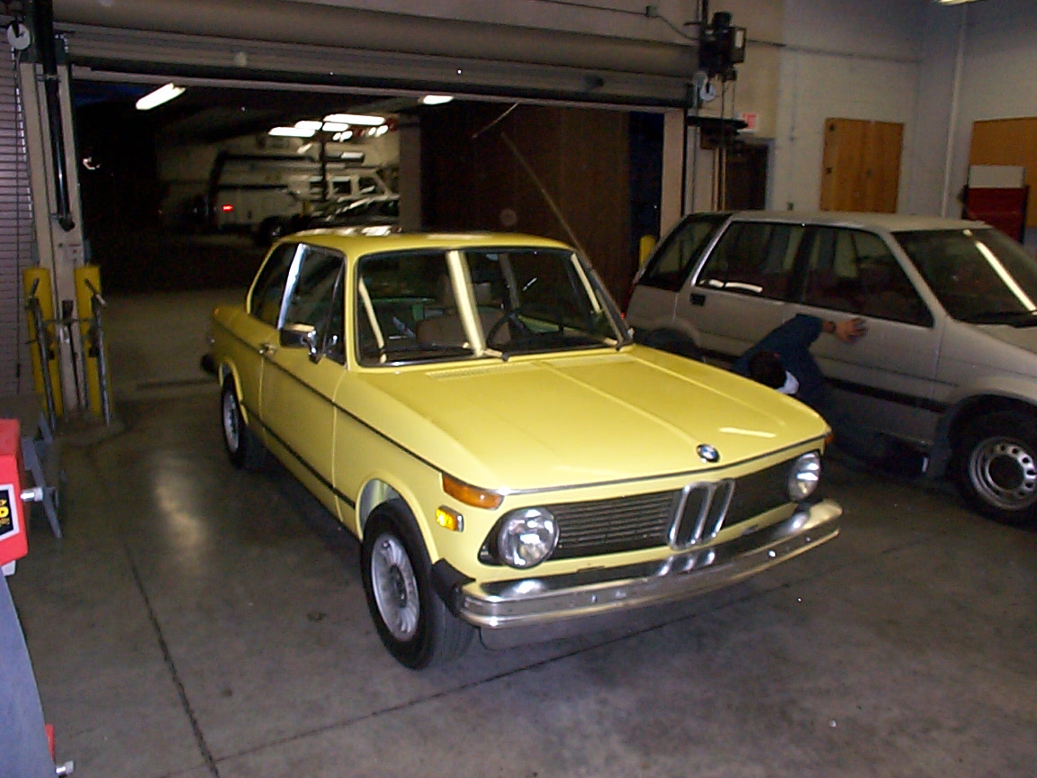
this is a picture of Leo's fine yellow electric beemer (bimmer?)
this is a picture of Leo's fine yellow electric beemer
this is a picture of Leo's fine yellow electric beemer
this is a picture of Leo's fine yellow electric beemer
this is a picture of Leo's fine yellow electric beemer
this is a high res pic of leo's classy looking electric BMW. Unfortuantely I think my finger was covering the autofocus sensor, as it's a little out of focus. We'll try again next week
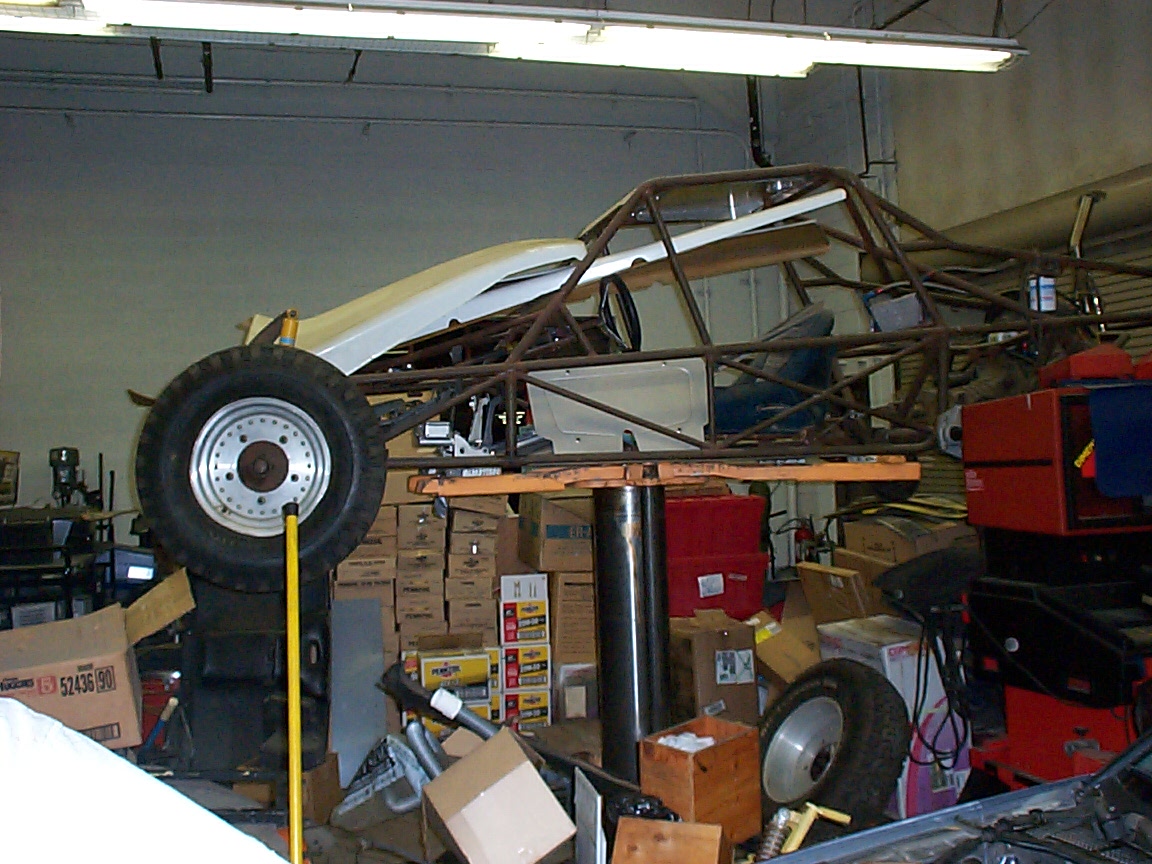
this is a go-kart that is slowly moving towards potentially being a EV. Maybe. Don't know.
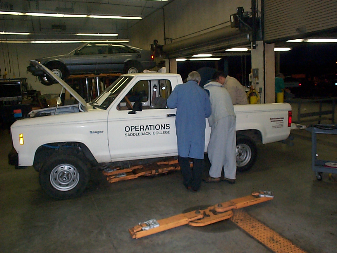
this is the electric pickup truck, with a distinct lean to it (it's getting bigger and heavier batteries, and right now they're all in the back along with a couple of students.
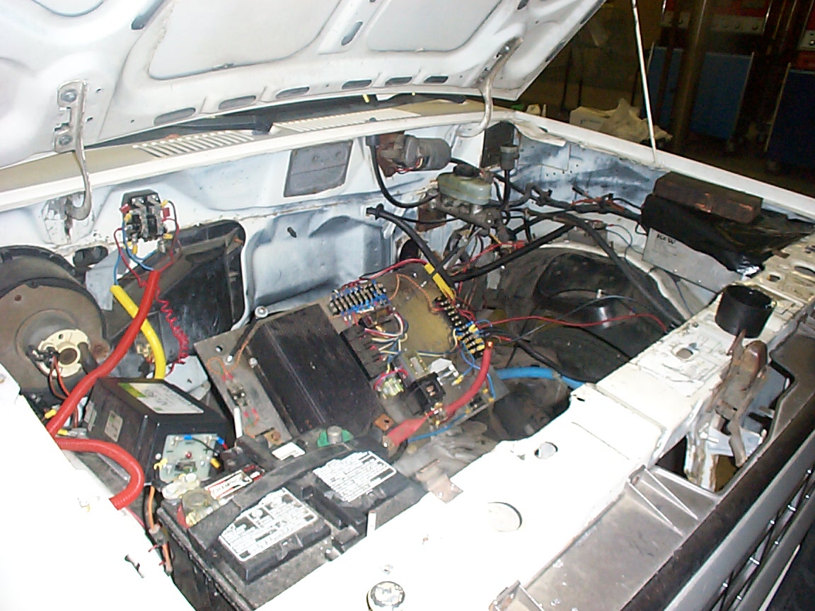
under the hood of the electric pickup, although things are currently being worked on.
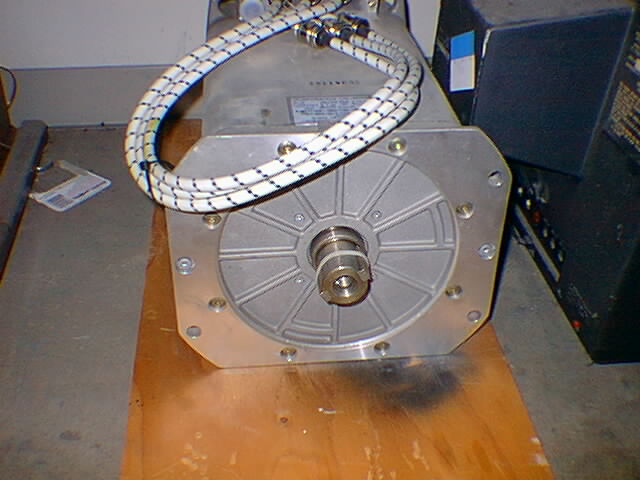
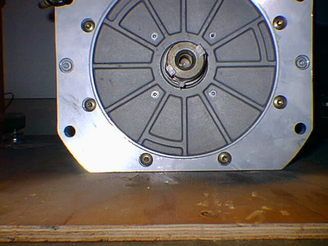
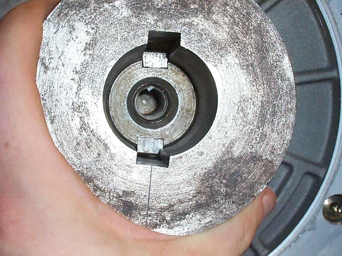
this is a picture of my AC motor, with the facing showing
this is a picture of my AC motor, with the facing showing,closer up
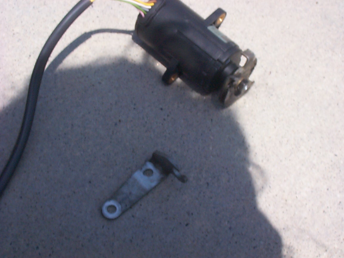
this is a closeup of the old throttle spool. We will try to recycle this for the new TPS, as the throw is almost exactly the same. (How convenient)
this is a blurry closeup of the old throttle spool, modified and mounted on the new throttle sender, and the throttle clip. I need to make a mounting arrangement that allows the throttle clip to be held 4.75" away from the TPS.
this is a first-generation eyeball-engineer special throttle bracket. Good enough to test with.
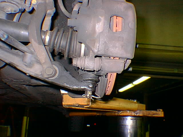
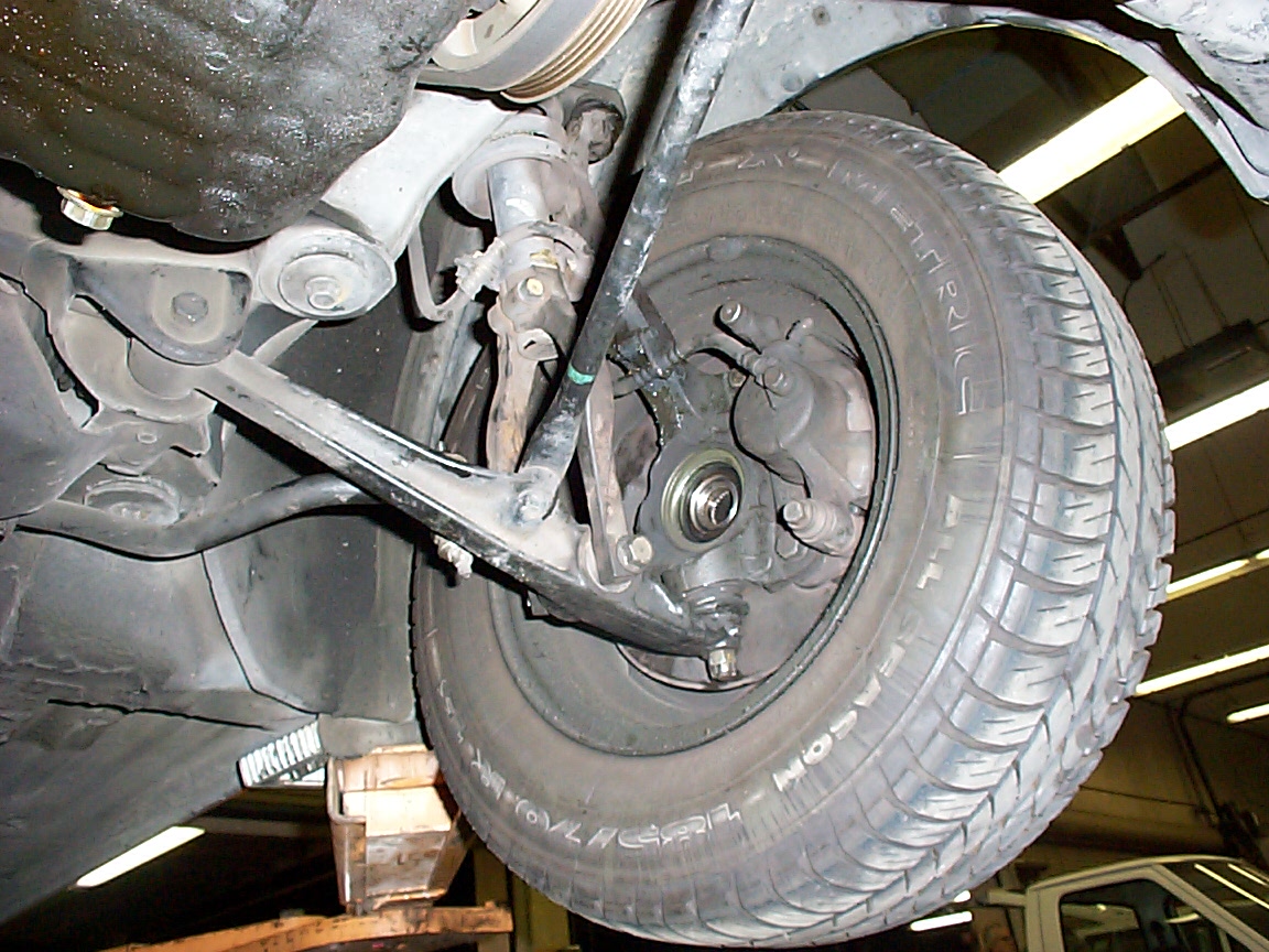
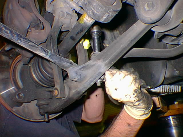
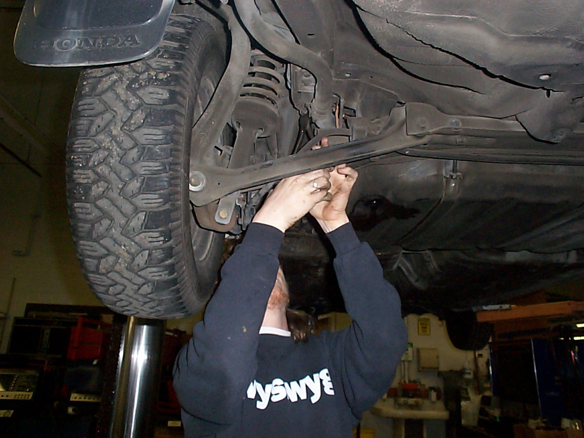
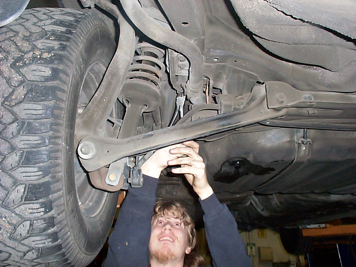
this is the suspension, showing the lower control arm, and reminding me to get a new cotter pin. ;-) I also need two new shaft-end bolts
Sheer explains how to R&R Honda CV joint so he don't forget
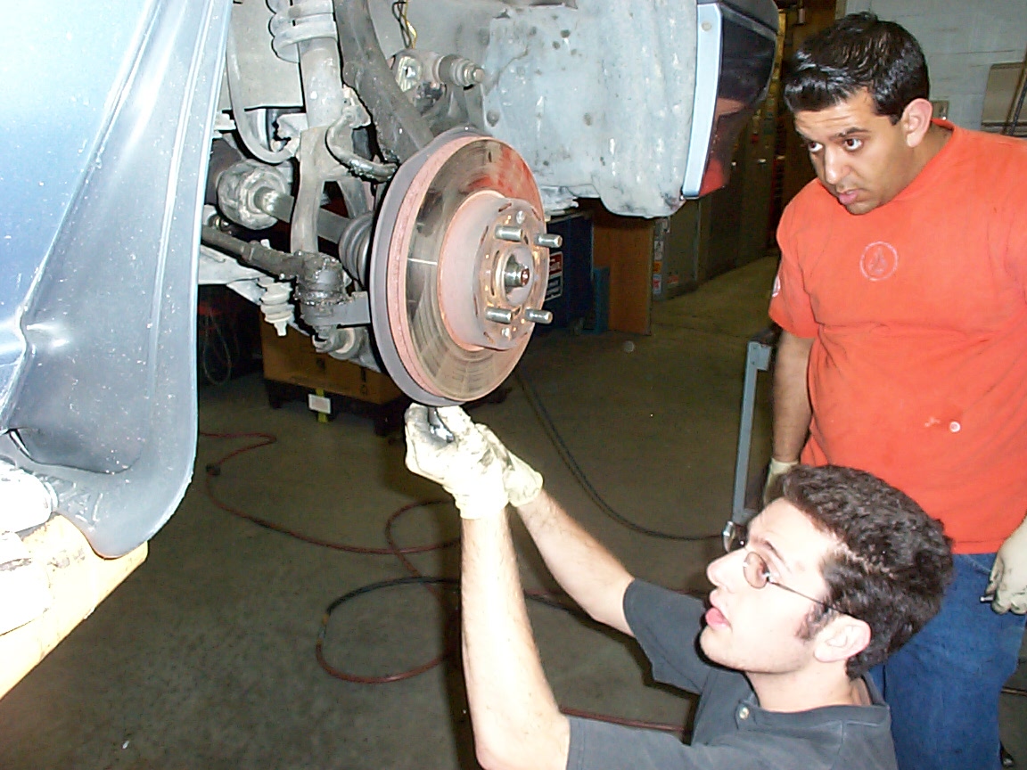
this is a high res pic of the passenger-side CV joint post center-bolt removal but prior to CV removal. Note that it's best to leave the caliper on while removing the center-bolt so you can use the brakes of the car to hold the disc in place
this is a high res pic of Josh preparing to remove the castle nut off the lower ball joint.
this is a high res pic of the driver's side wheel well, reassembled sans CV
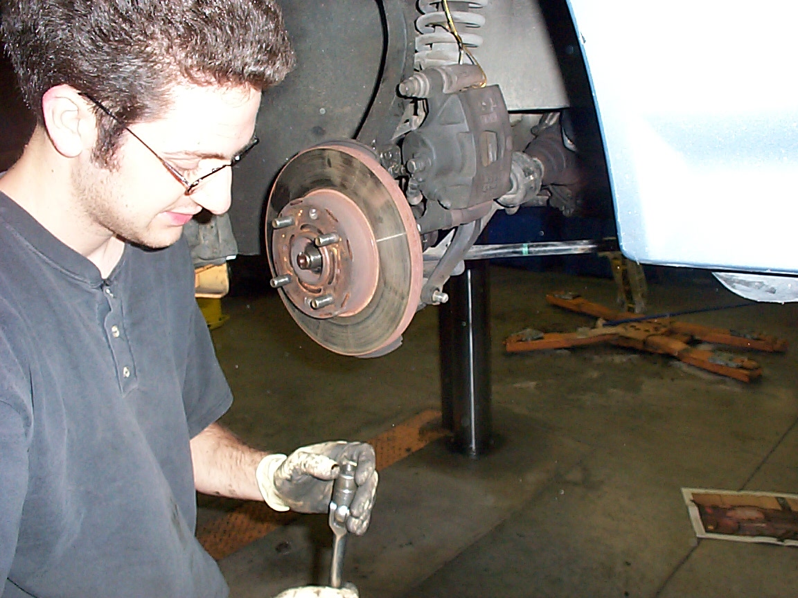
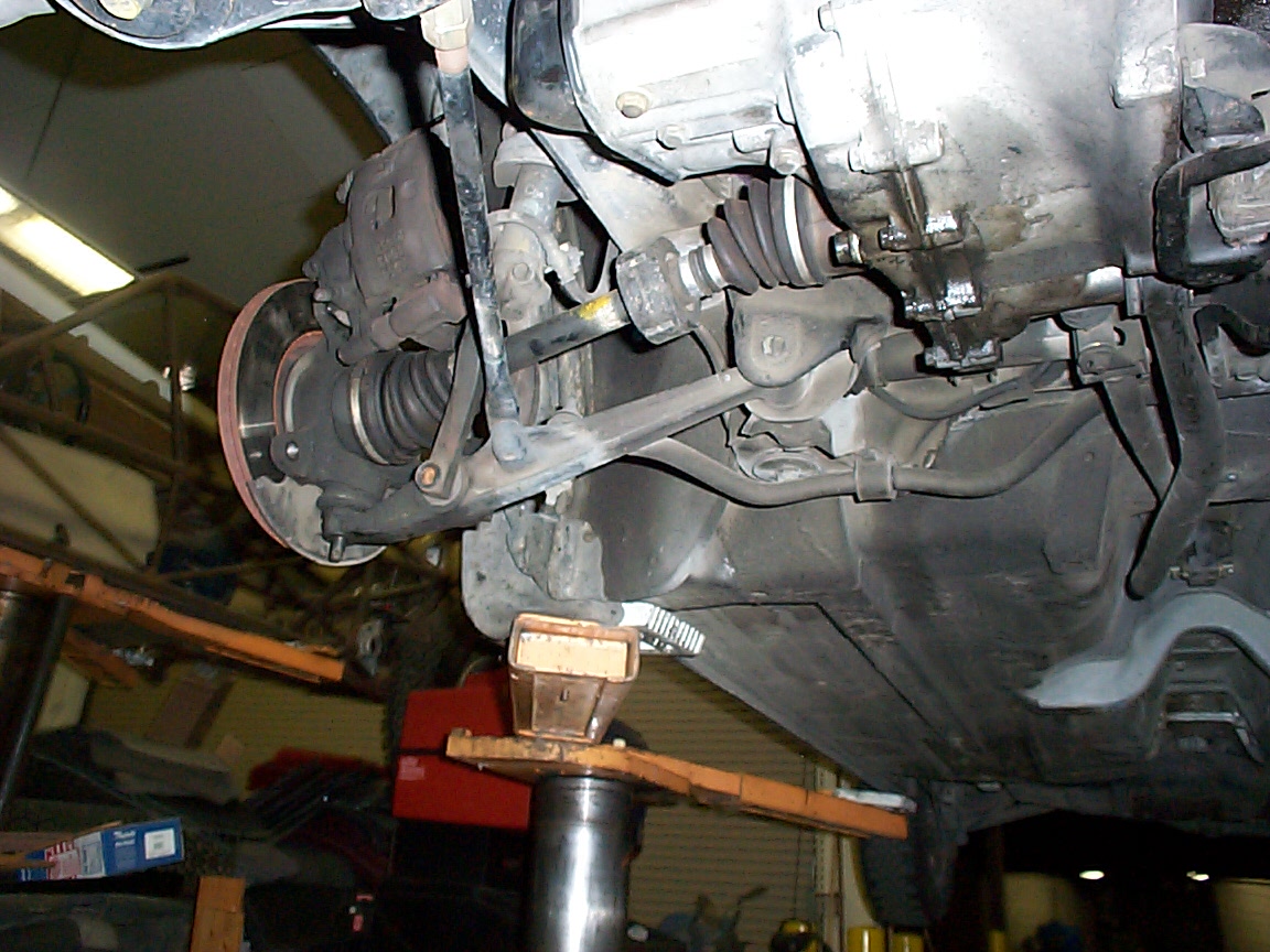
this is a high res pic of the passenger's side wheel well with CV still in place
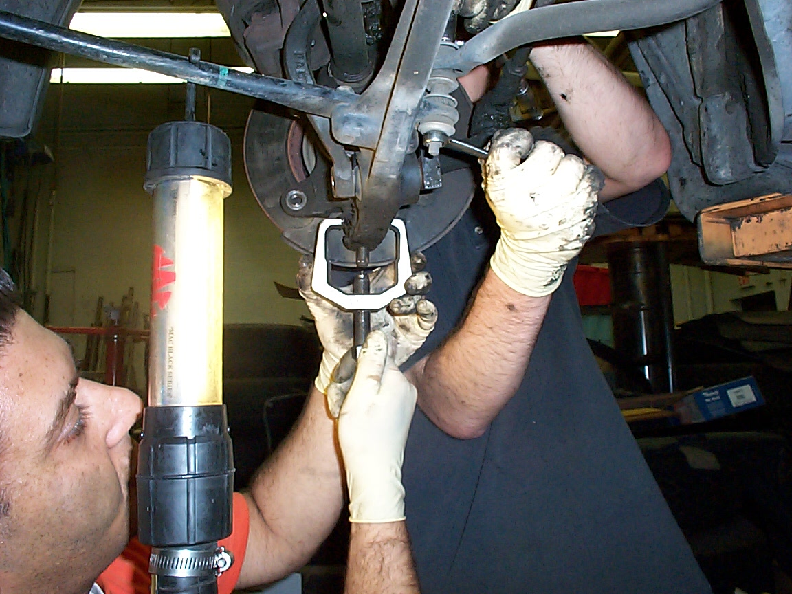
this is a high res pic of the bearing puller removing the ball joint
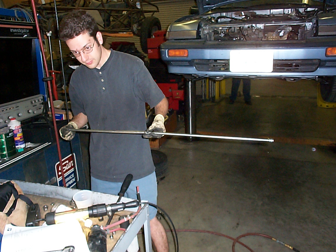
this is a high res pic of the longest extension you've ever seen. We needed this to remove the shift linkage (From the top) because removing it from the bottom just wasn't practical.
this is a high res pic of what is soon to be a hybrid honda (maybe)
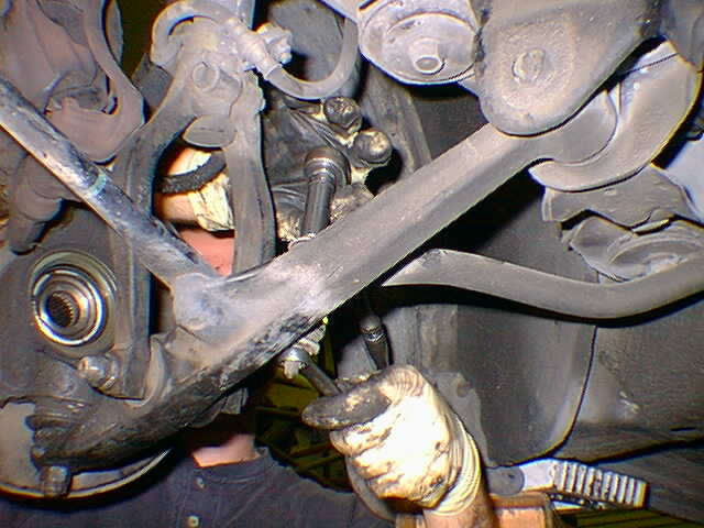
this is another shot of the passenger side CV, as Jon was removing the bushing attachments to a tie rod (i think)
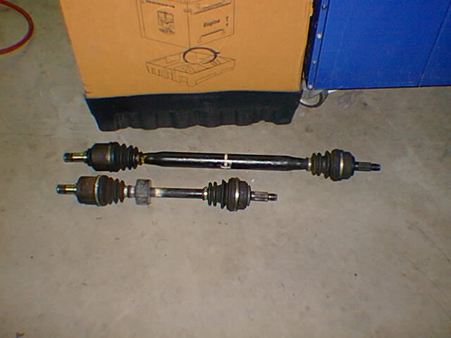
this is the removed CV joints.
this is Jon reassembling the bushings
this is a high res pic of Jon removing the bolts for the engine mounts.
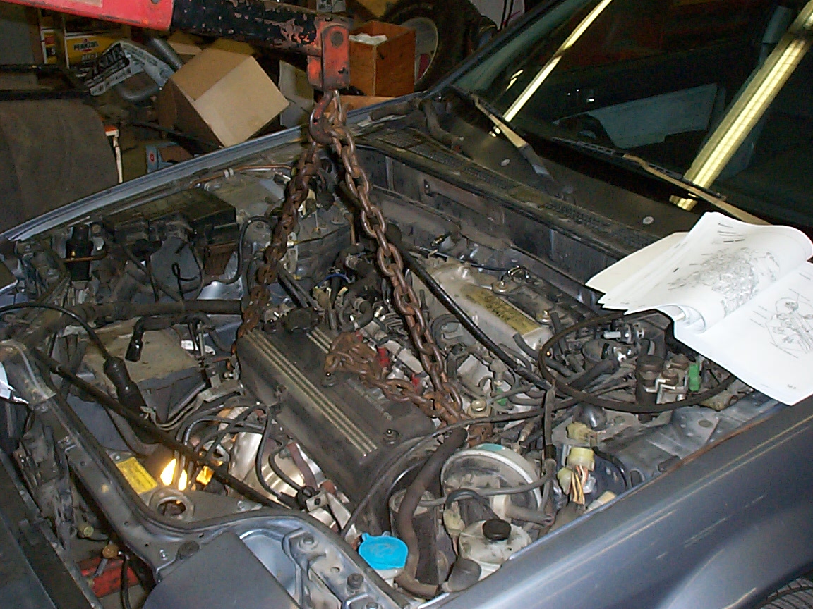
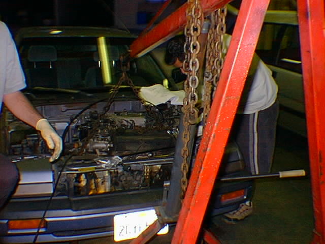
this is a high res pic of the engine all chained up for the first of three attempts to remove it.
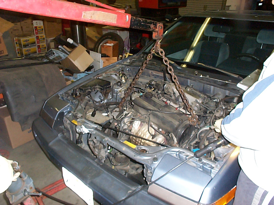
this is a high res pic of the engine starting to move.. unfortunately we had the chain rather in the wrong location and so the assembly was not coming out anything like straight.
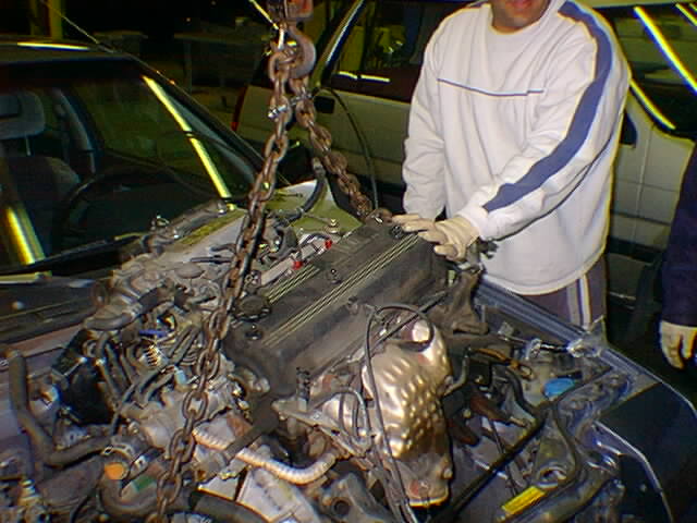
this is a high res pic of the engine, finally obtaining some altitude.
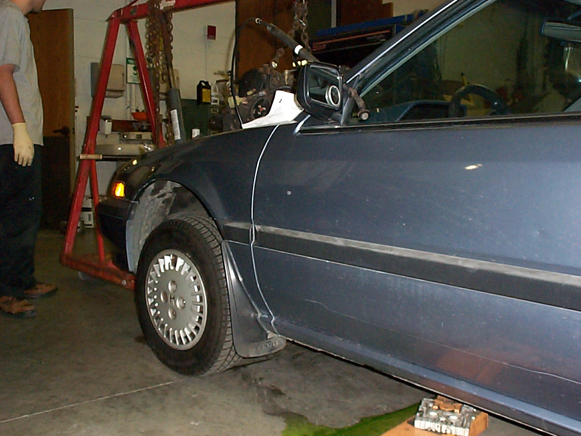
this is a a high res side shot of the car, showing the engine in varying stages of not-quite-there-ness.
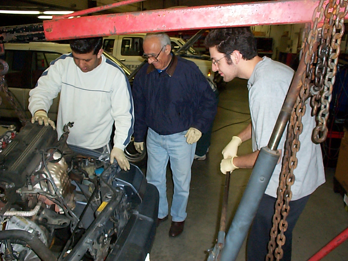
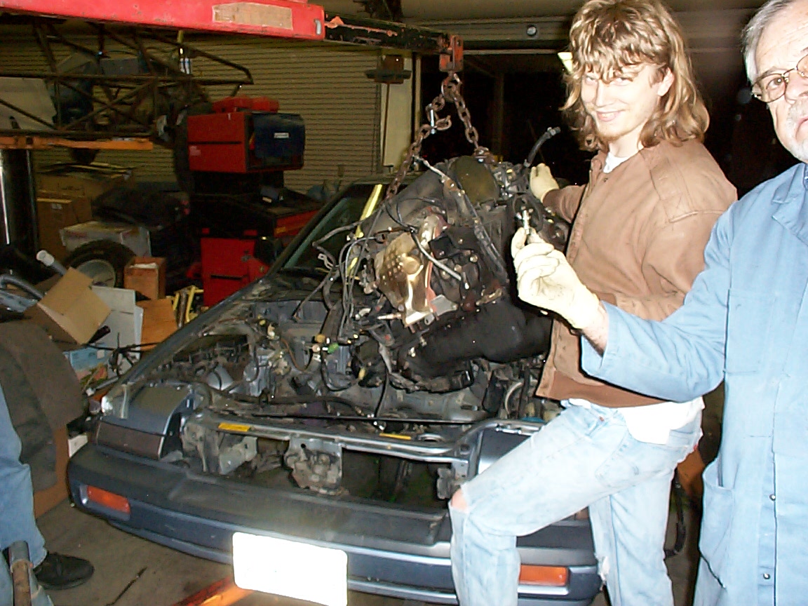
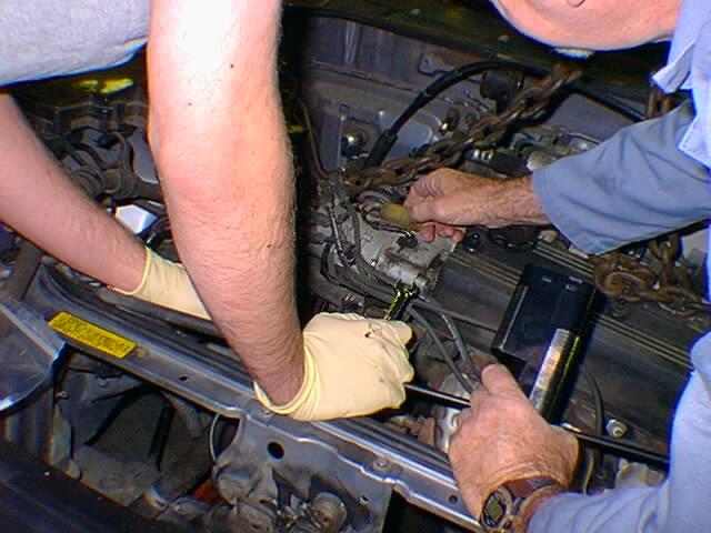
this is a high-res pic of me stablizing the engine after it has been transferred from engine hoist to engine hoist several times, while the Prof shows the one bolt that held the whole thing in. Incidentally, the man next to me (Prof McFarland) probebly saved at least four fingers and five hours during the removal of this engine - I can't say enough about how helpfull his experience with all things mechanical has been during this project, especially the stage we just completed. Literally I do not think this engine would have come out without his help and advice.
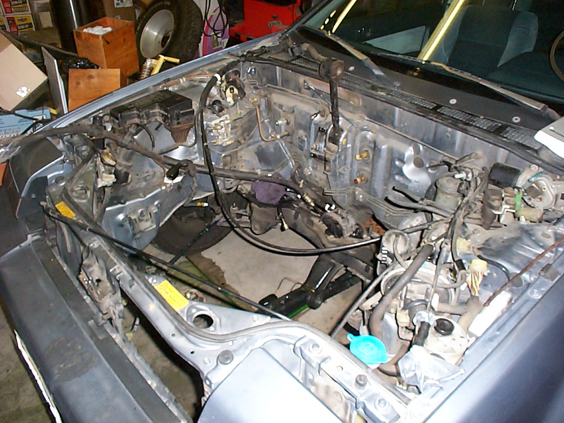
this is a high res pic of the resulting engine compartment. Wow, it's empty in there..
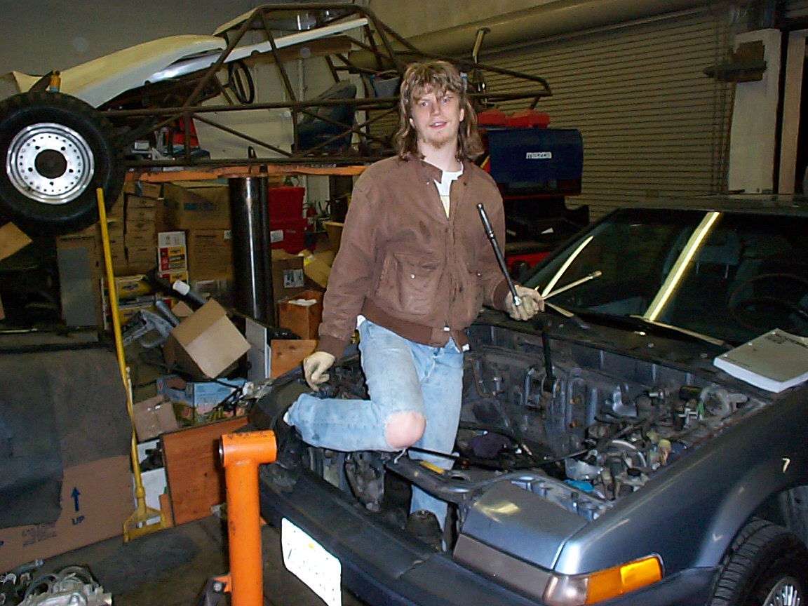
look at this high res pic of the new propulsion model.. you just sit down and push.. ;-)
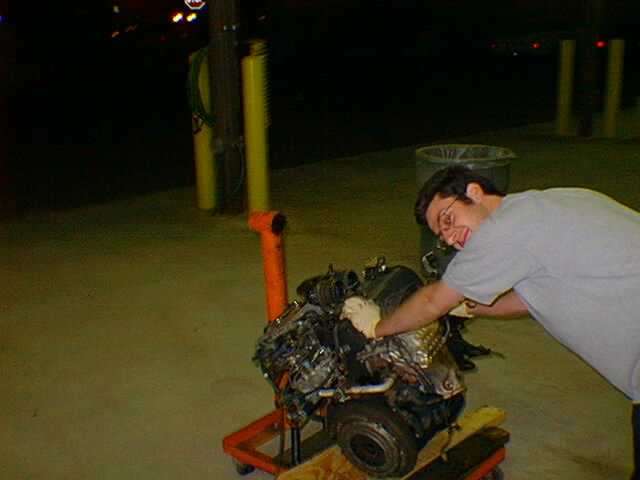
this is a high res pic of the engine on the ground, with all the hoses, wires, et al that this involves. By the way, you would not _beleive_ how much antifreeze manages to hide out inside your average engine..
this is us frantically removing the distributer, after realizing that despite the fact that the book doesn't mention it, it really does have to come out
this is the engine hoist, all set to lift for phase one
this is the engine mount that was preventing the engine from popping straight up. A few bolts removed, and whala.. no more problem there.
this is the engine in the first stage of ascension
this is one of those pictures that I don't know why was taken..
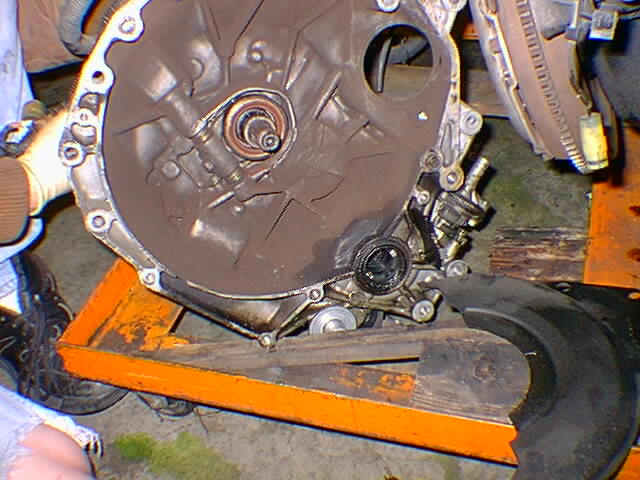
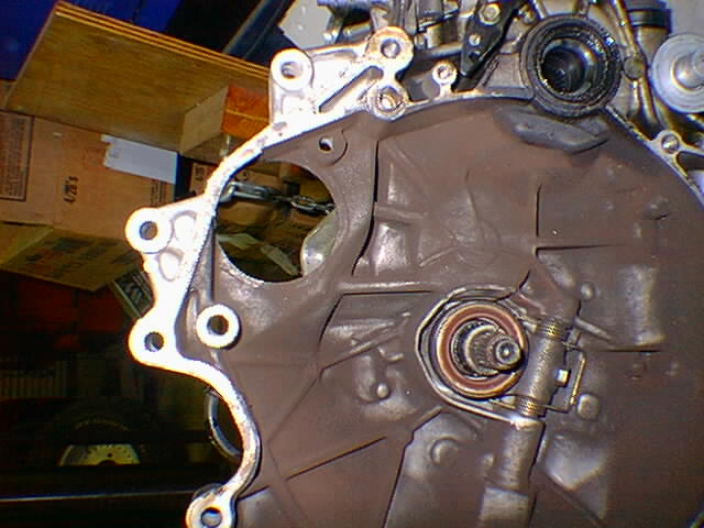
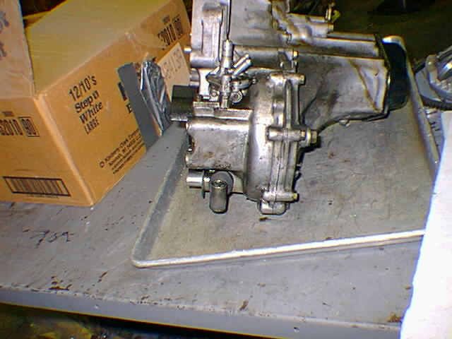
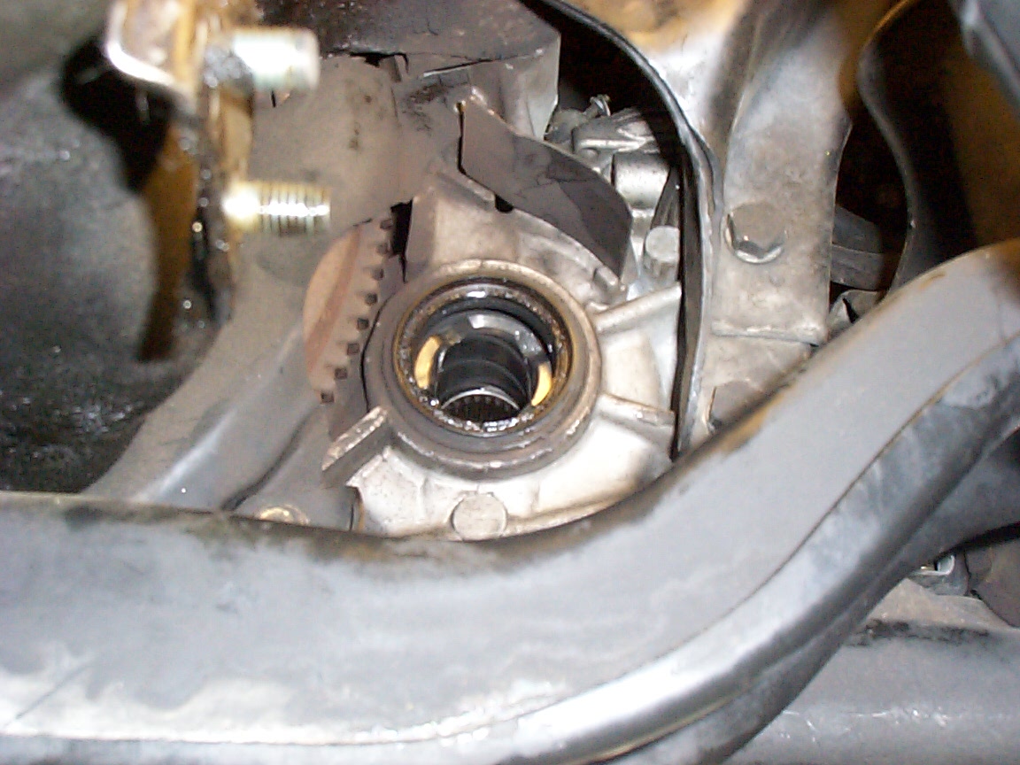
this is the side of the transmission that faces the flywheel, immediately after removal. That oily spot on the bottom is the driver's-side CV socket. the whole is where the starter used to mount.
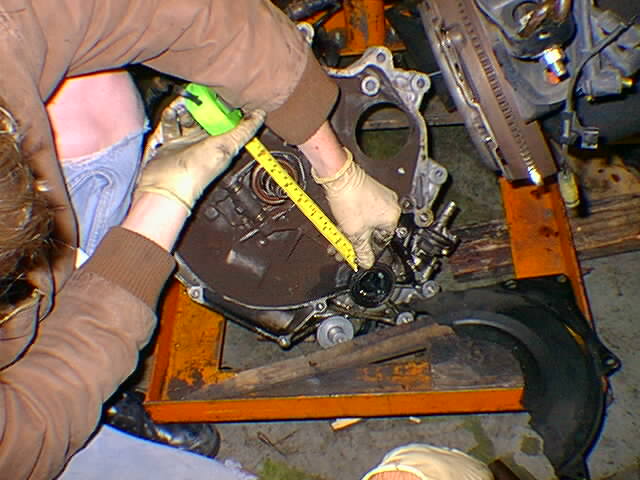
this is us measuring to make sure the motor will fit. Ha ha ha. Aren't we funny. What would we have done if the answer had been no? ;-)
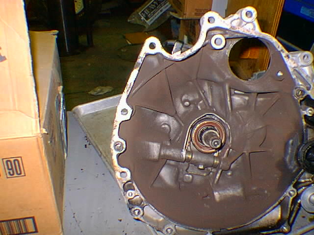
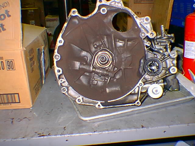
this is another shot of the transmission motor facing.
this is yet another shot of the transmission motor facing.
this is yet another shot of the transmission motor facing.
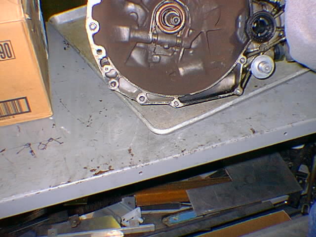
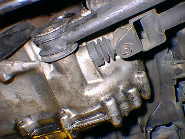
this is yet another shot of the transmission motor facing. that funky thing under the CV is the place where the gearshift gets connected
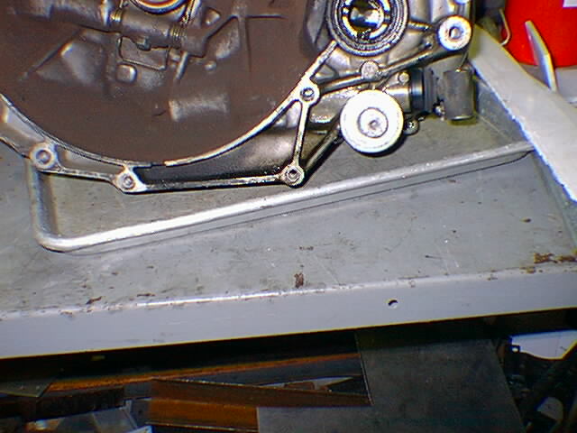
this is yet another shot of the transmission motor facing. that thing sticking out above the CV is the speedo/VSS linkage, and also connects to part of the power steering system for reasons that aren't neccesarily crystal clear.
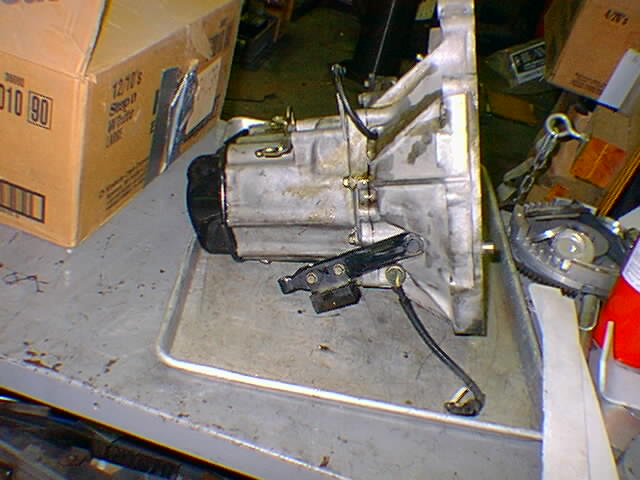
this is the tranmission, from the side. Small and light, suprisingly.
this is the tranmission, from the other side. that cable hanging off is the reverse sensor, and that big lever is the clutch.
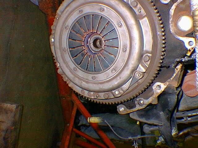
this is the clutching surface of the flywheel. Okay, you all knew that.
this is josh taking the engine for a little ride to its new temporary home. Hey, anyone want to buy a 1986 Honda Accord engine, cheap? it runs..
this is the driver's side of the engine compartment, sans engine
this is the passengers's side of the engine compartment, sans engine
this is a closeup of the shift linkage
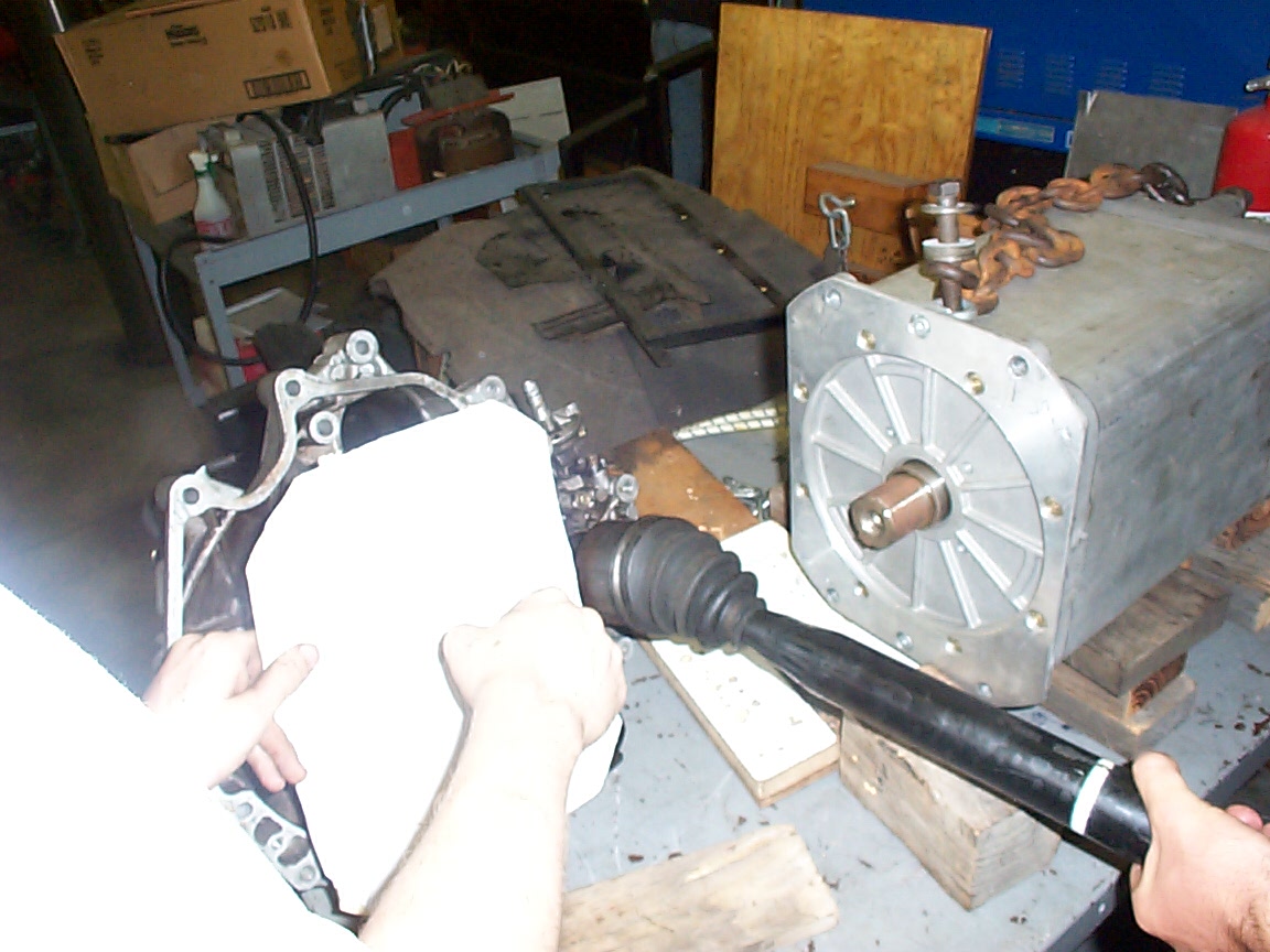
this is a high res closeup of the CV socket on the motor facing side. This shows the tightest fit in the whole mess (thus far) where the adapter will have to be very carefully made.
Car pics, engine removal
Shift linkage
Adapter plate app note pics
VSS stuff
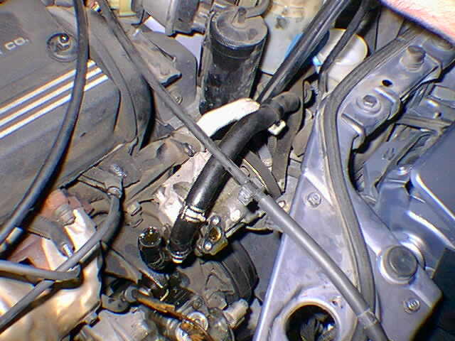
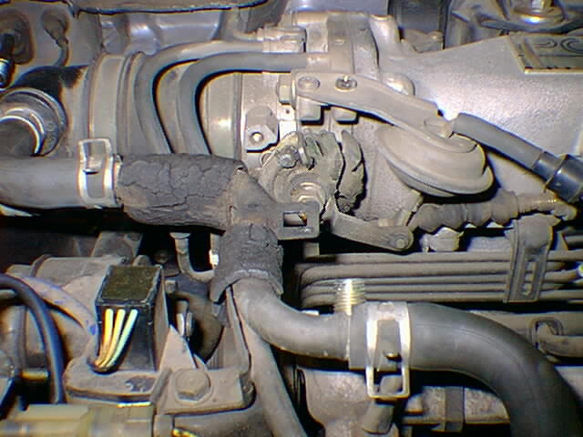
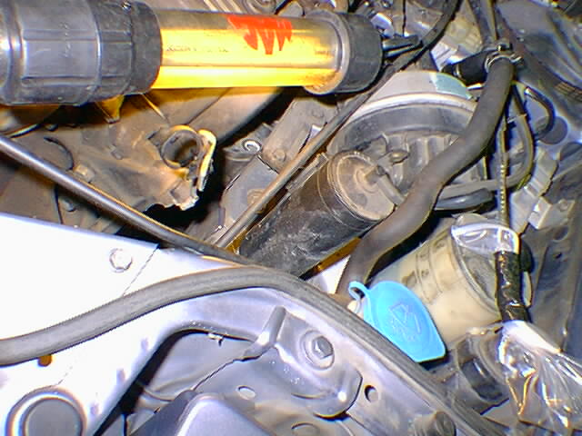
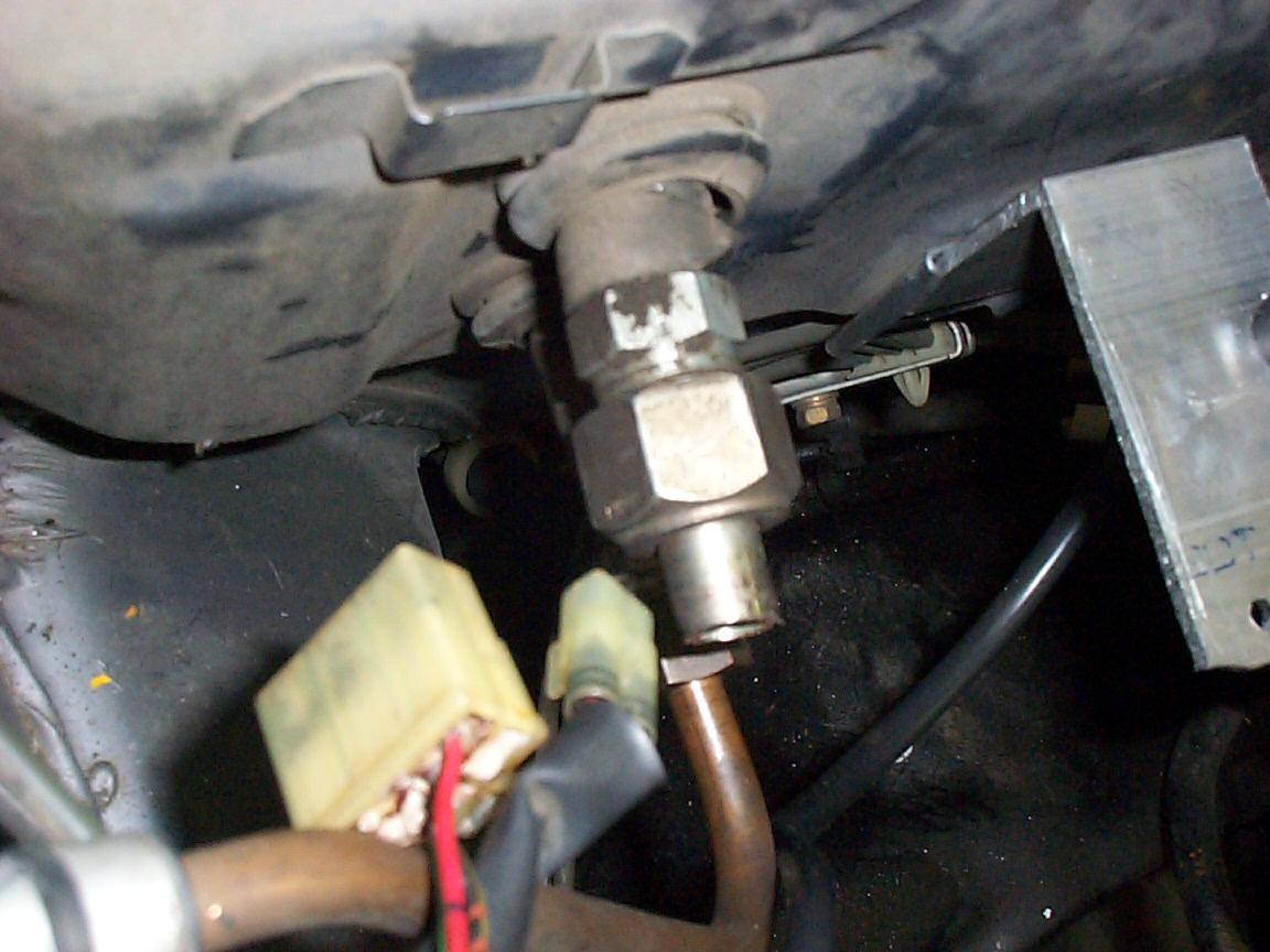
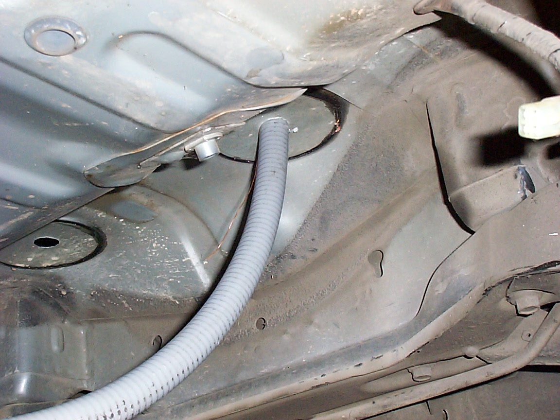
this is a shot so we know which hose from the p/s system goes to which side of the speed sensor
this is a shot so we know which hose from the p/s system goes to which side of the speed sensor
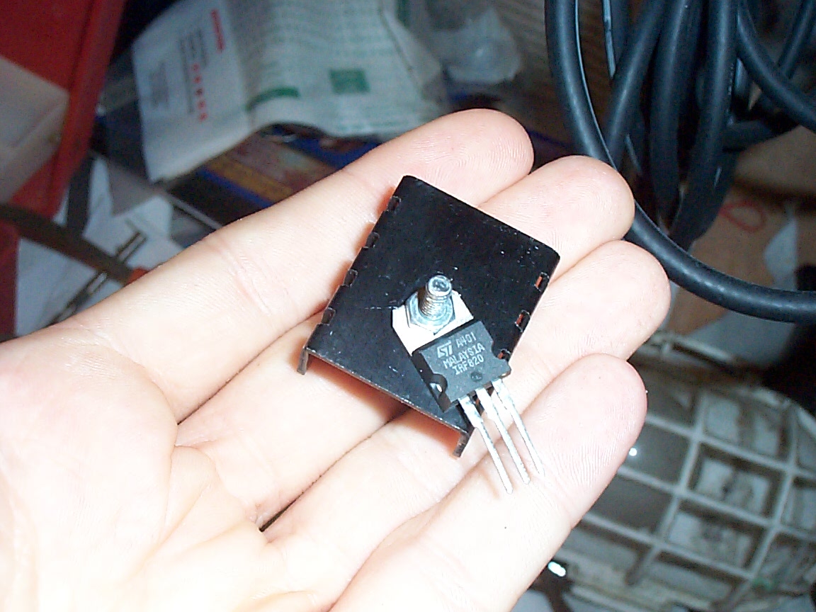
this is a high res pic of the handy $1.00 MOSFET that switches the current into the battery. This heatsink may be a little small for it though, it gets pretty hot in use. Then again, it hasn't gone POP yet. But I'll probebly upgrade as soon as I can order some new heatsinks.
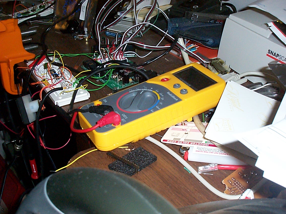
this is the RS232 sampling voltmeter that collects the single cell voltage data. That thing next to it is a basic stamp in a carrier, connected to my prototyped UI (the meter and the PCB next to the basic stamp), my prototyped battery cell measurement circuit for lead acid systems (the op amp and 2:1:1:2 transformer. Don't ask. You do NOT want to know. It's ugly. But it works really, really well.)
this is the other half of the voltage sampling circuit - the calibration and comparison matrix.
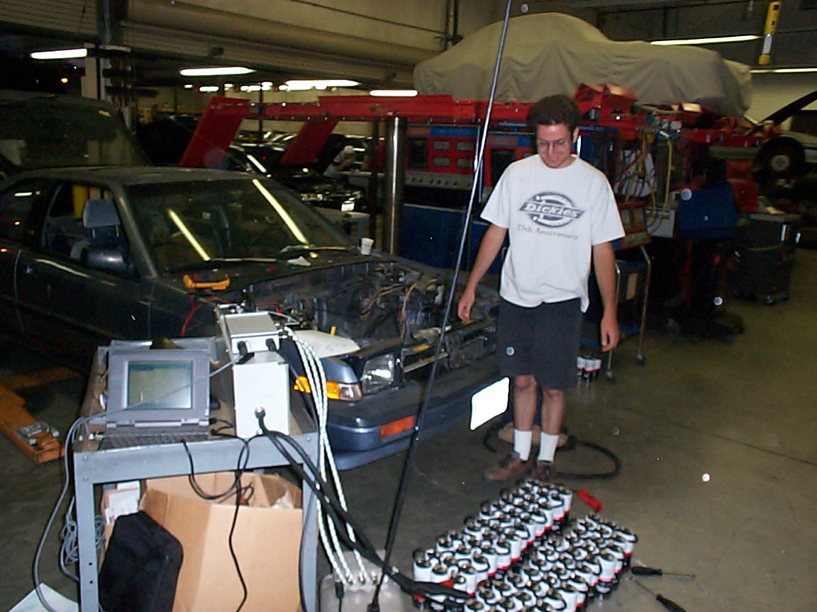
halfthe pack has been levelled (takes about 2 hours a unit, give or take
the packhas been completely charged. Levelling is proceeding nicely. They're about ready to become part of a string
this shows the first preliminary rough measurements of the cells to determine how to make the 'bus bars' - because I will have 140 of them, they will need to stay on on their own. Belvilles are all well and good, but I think I want something more aggressive.. like maybe Loctite? Since they're PbA batteries, maybe that wouldn't be such a good idea - though they sure don't act like lead acid batteries.
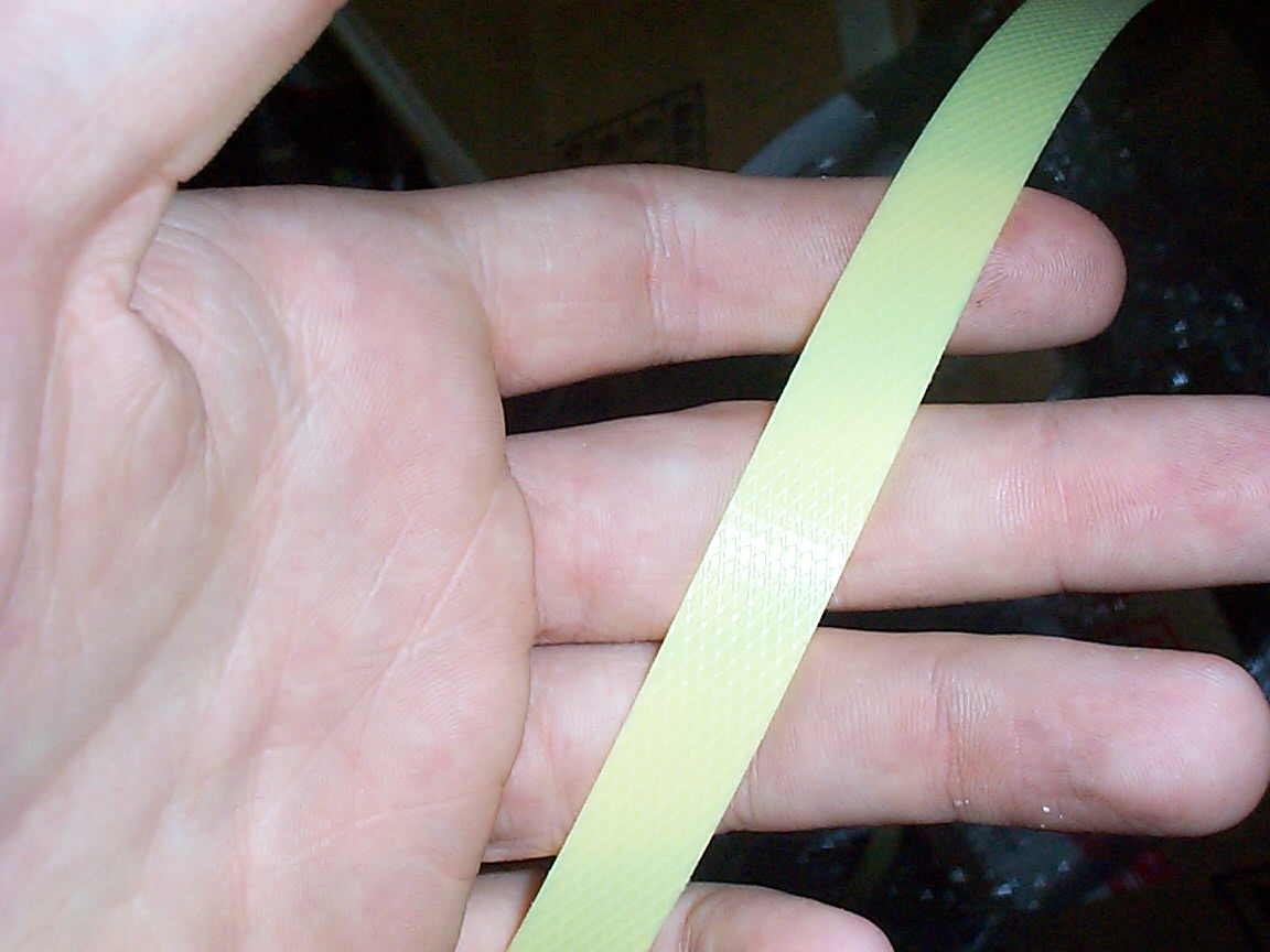
this is the fiberglass(?) strapping I would like to use to assemble the cells into packs
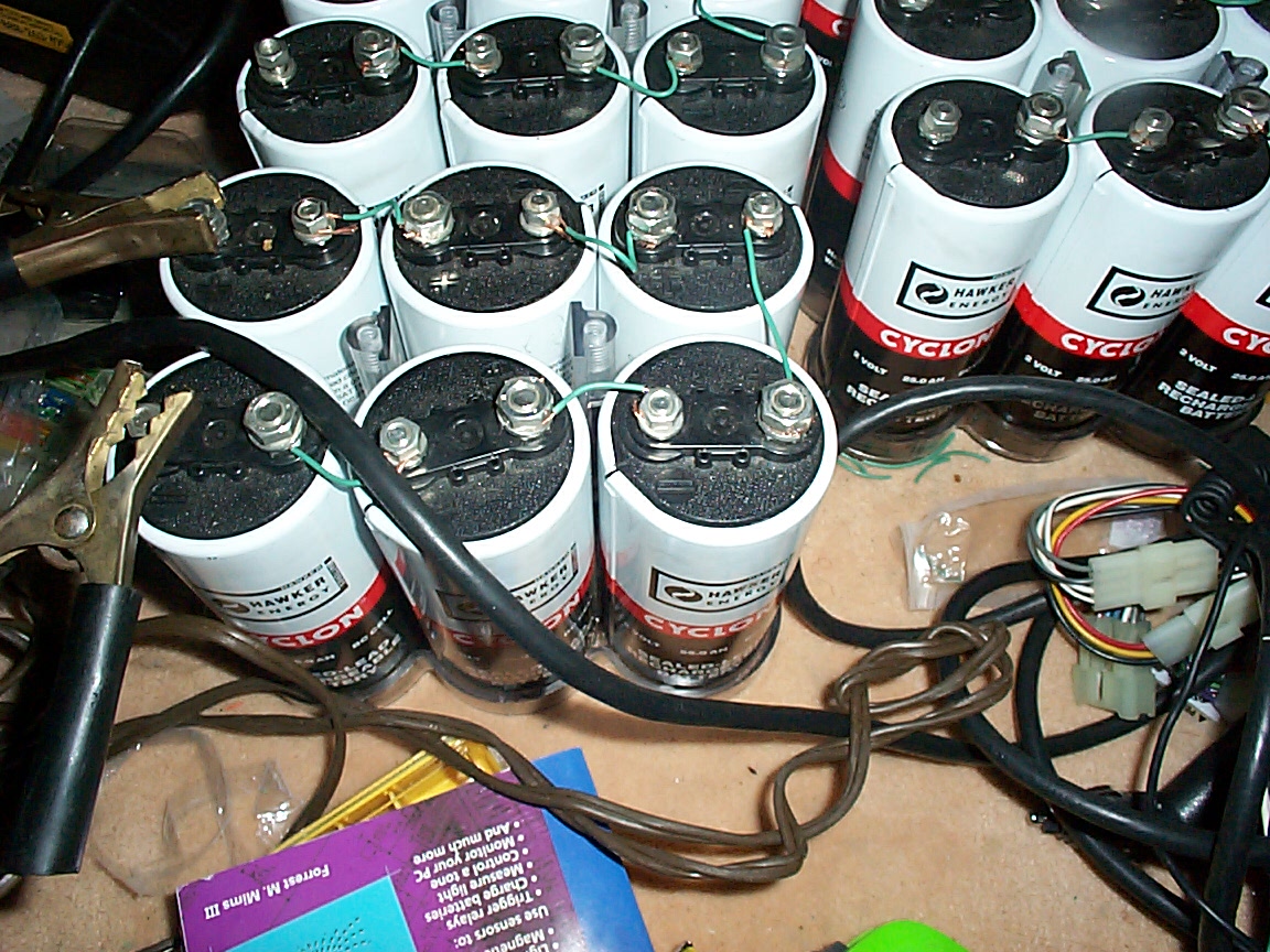
this is a 'six pack' of cyclons being drained for the total-cycle test.
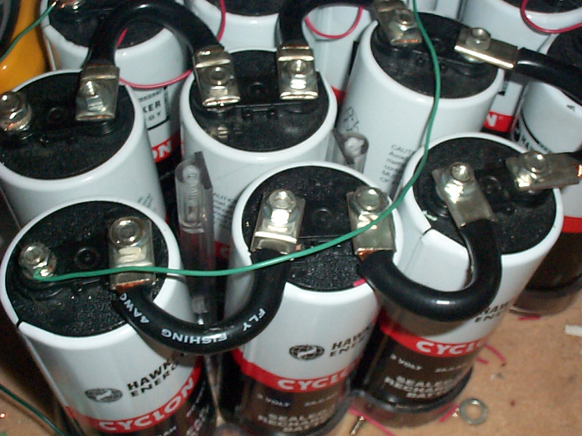
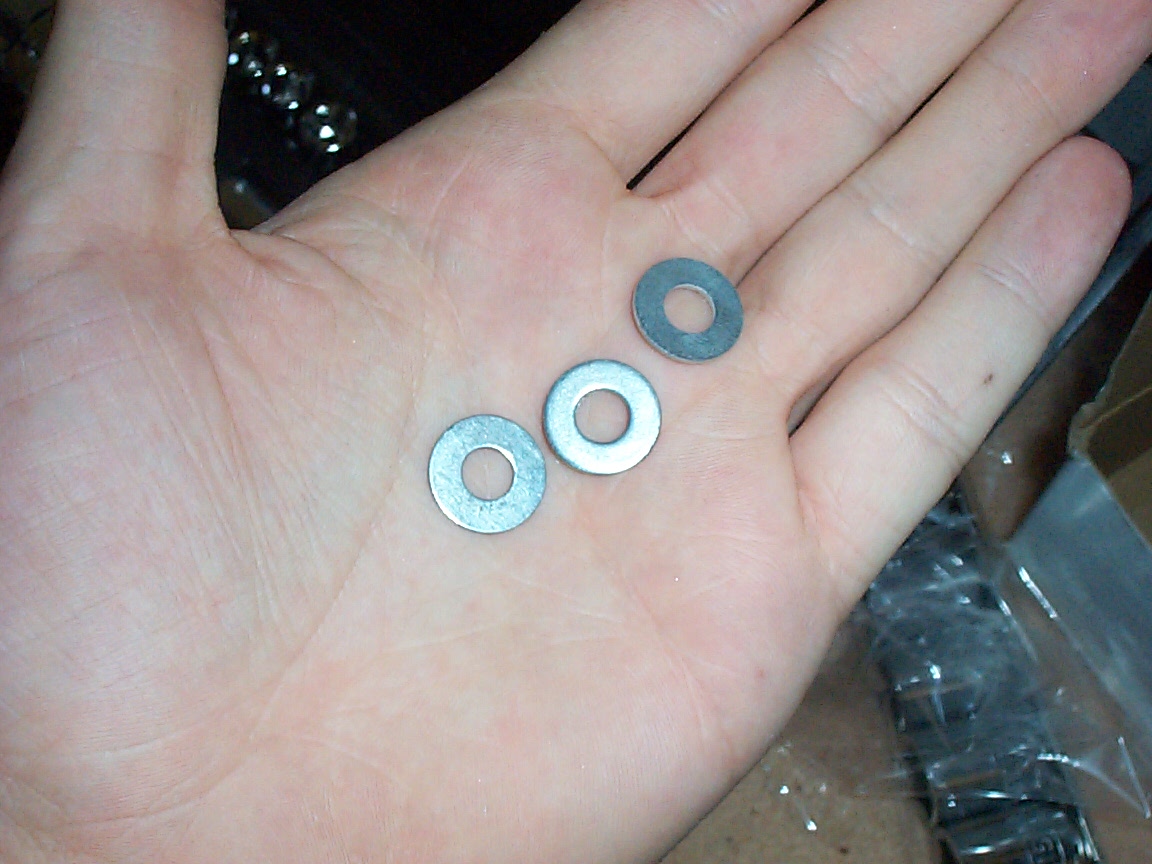
this is a high res pic of a six pack of cyclons rigged for high amperage. No more wussy little wires ;-) this is a picture of the washers which solved my post meltdown problem (at least for now)
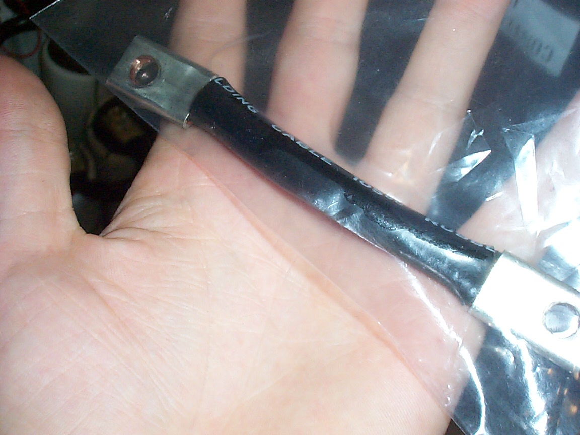
this is a picture of one of the high power straps that tie the cyclons togeather now. These wires are a bit of a mystery - they have '4 AWG' printed on the side of them, but all indications are that they are 2 AWG, and they were sold as 2 AWG at a surplus place. I'm suspecting that they wound up as surplus because of some kind of labelling screwup.
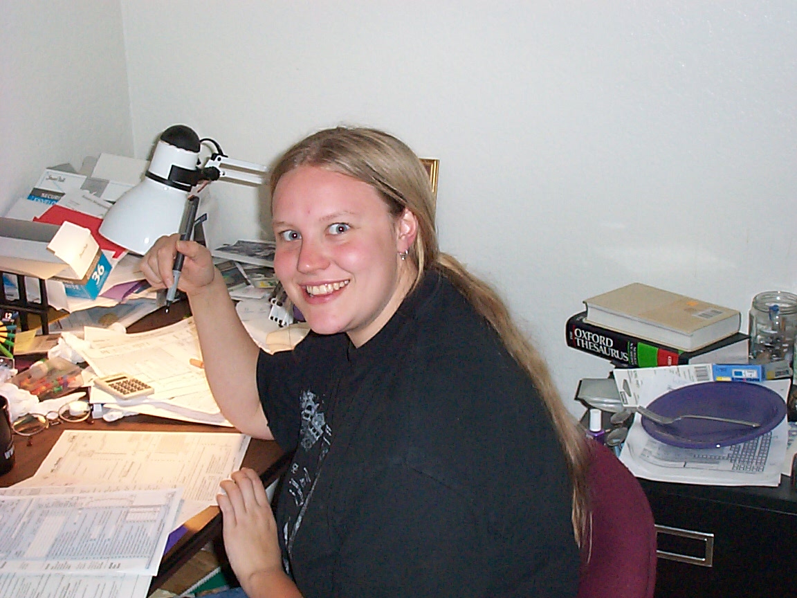
my long suffering girlfriend dealing with the taxes. (isn't she great?)
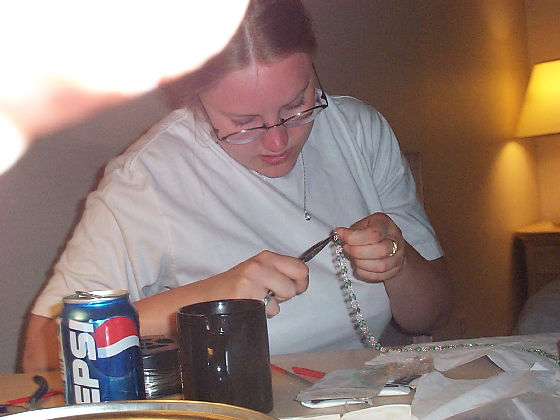
as you can see her hobbies also involve bending little bits of wire around - just in a very different way.
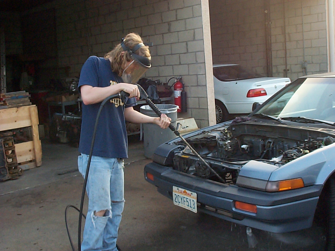
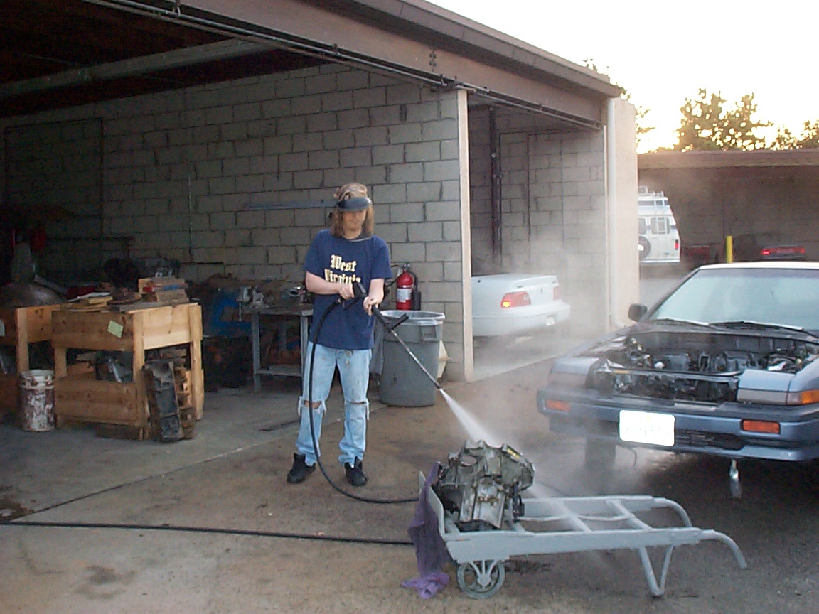
At the carwash being steam cleaned.
It's my down-home moment steam cleaning the car in a West Virginia shirt.
Steam cleaning the transmission, with rags carefully stuffed in the two CV joint holes - later we replaced them with plastic bags. You do NOT want to get the inside of your tranny wet.
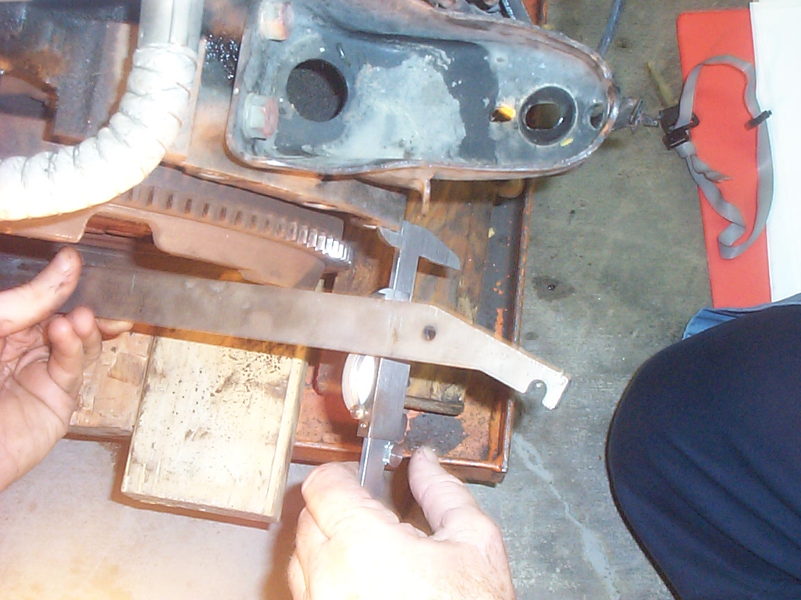
getting the 'magic number' (1.260"). The guage block is sitting on the machined surfaces where the clutch holder thingy screws screw in.
Gas Tank Removal
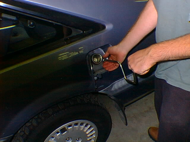
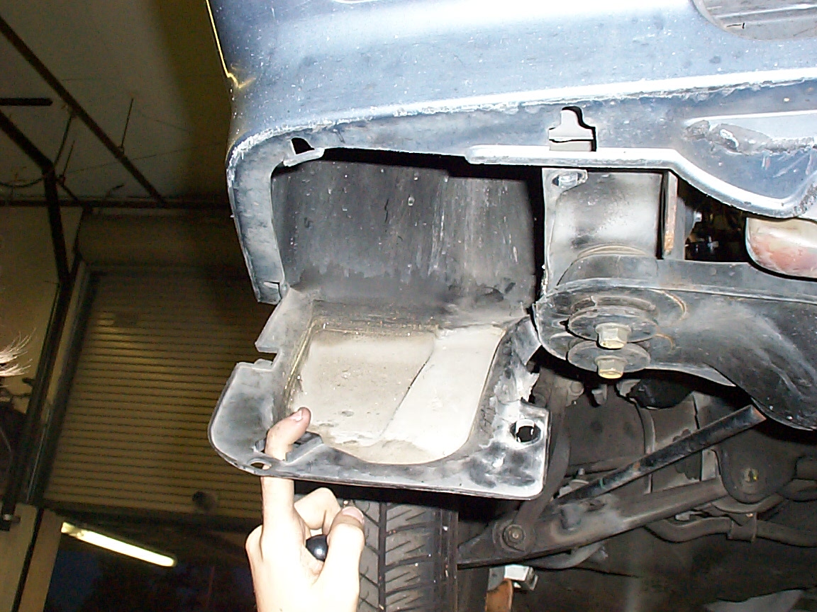
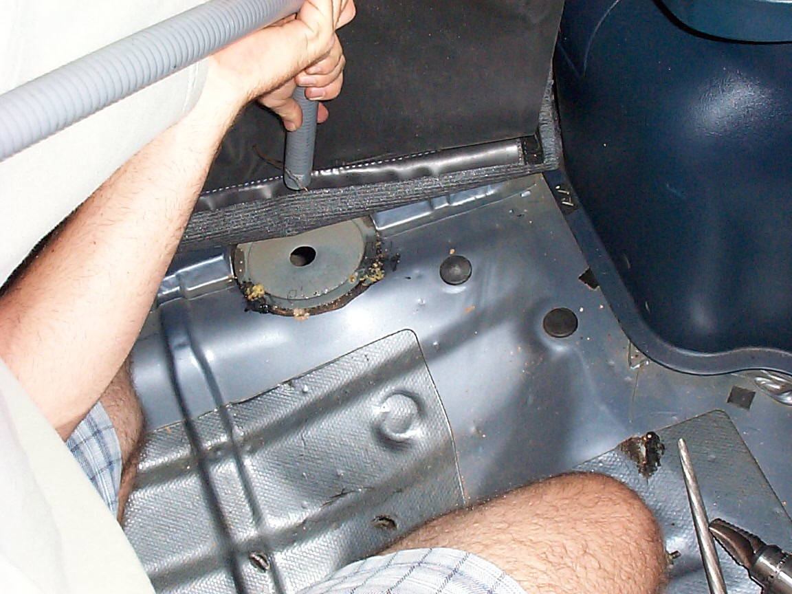
this is me removing the little cover that covered up all the fuel lines
this is me cutting some of the excess lines. Be aware, people, that it is not possible to remove a gas tank without getting at least half soaked in gasoline, which is one of the most vile, evil, and nasty substances known to man.
this is the drain plug, all ready to be removed to drain the gas.
this is breaker-bar-boy breaking the drain plug.
this is the beginnings of the gasoline flow
this is the gasoline running out of the tank, while josh carefully avoids getting more gas in his eyes. (Sorry, Josh..)
this is the fuel tank on the ground, having been successfully extracted from the car
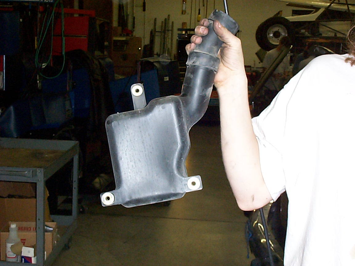
this is josh removing the fuel filler thingy.
this is the resulting hole. Maybe I can wedge a cyclon or twenty there?
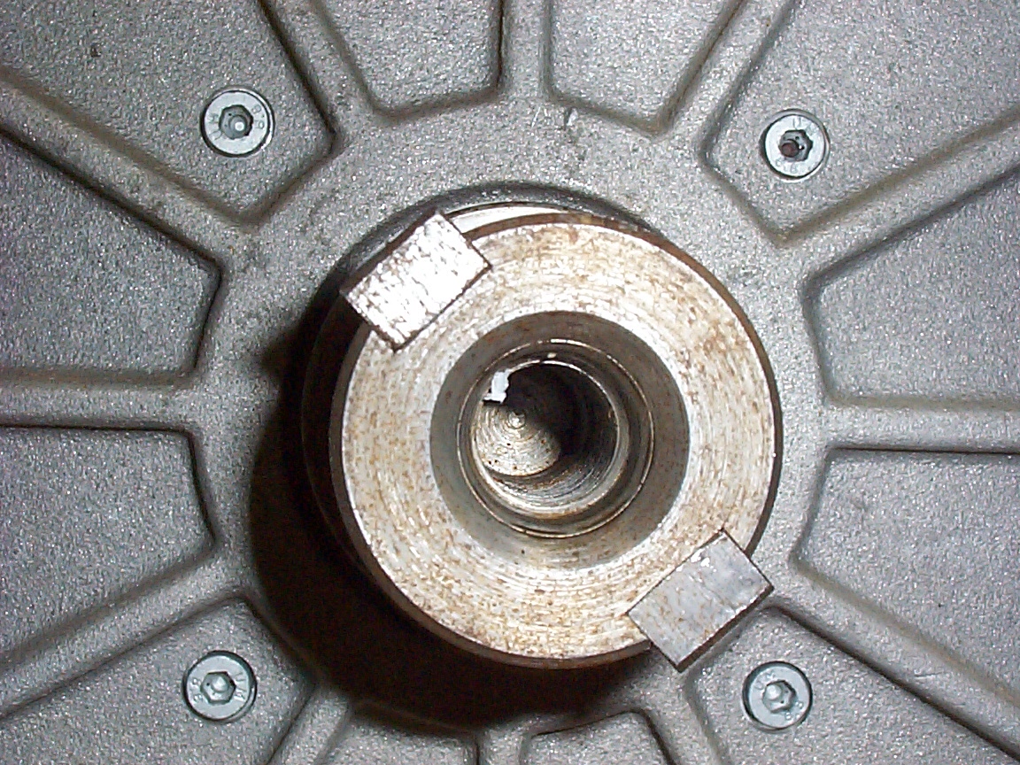
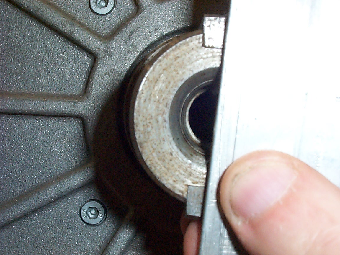
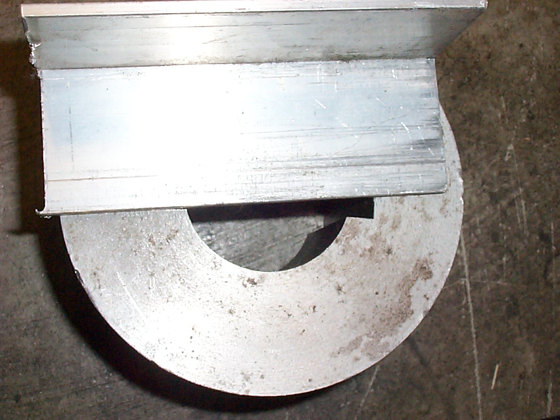
so we took lots of photos in the hopes that those combined with a few drawings will assist the machinist in fixing the problem. This one is a high res edge on closeup of the test slug trying to go into the motor shaft and not quite making it
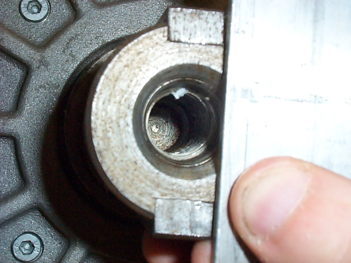
A high res extreme close up of the motor shaft.
I attempt to show that the two keys are 180 degrees around the circle from each other, rather than any other number, and that they're both on the centerline.
and I fail miserably - from this photo it looks like the peice should have fit. Hrm. Maybe I should go back to computer programming.
but here I'm pretty sure the problem is apparent.
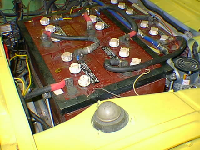
here is a high res pic of the dash warning light pigtail and the newly mounted 12V system battery
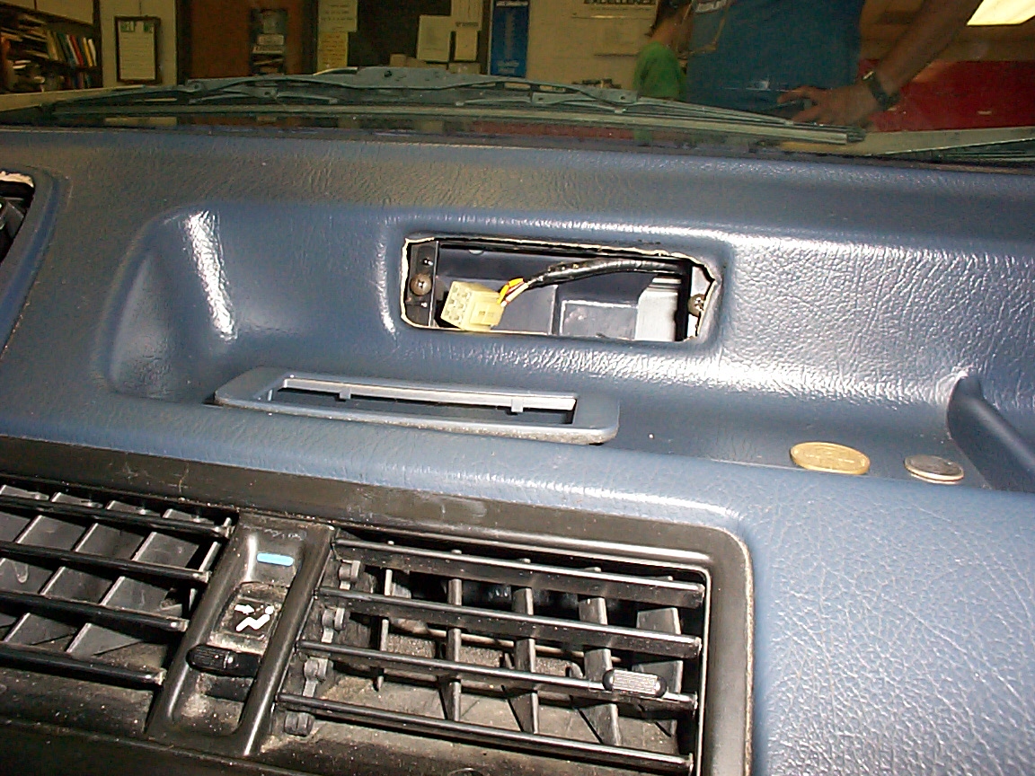
here is the place where the clock used to go. Soon a LCD module will go here instead. It'll be a clock - among other things.
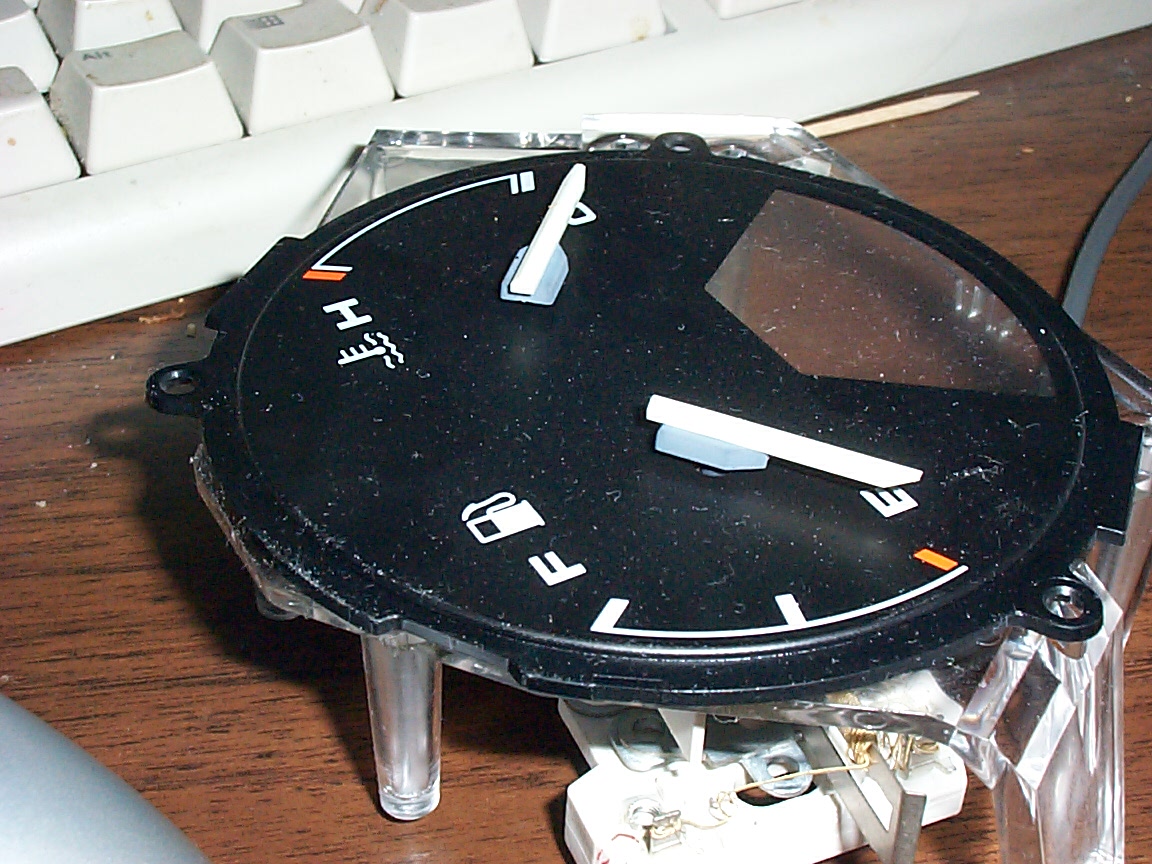
here is a high res pic of the two analog guages (heat based) that will be software drivable. I may also get irked and replace them with magnetic meters if I can figure out a way to do so.
here is a high res rear view of the two analog guages.. note the heater wires going off to the bimetallic strip.
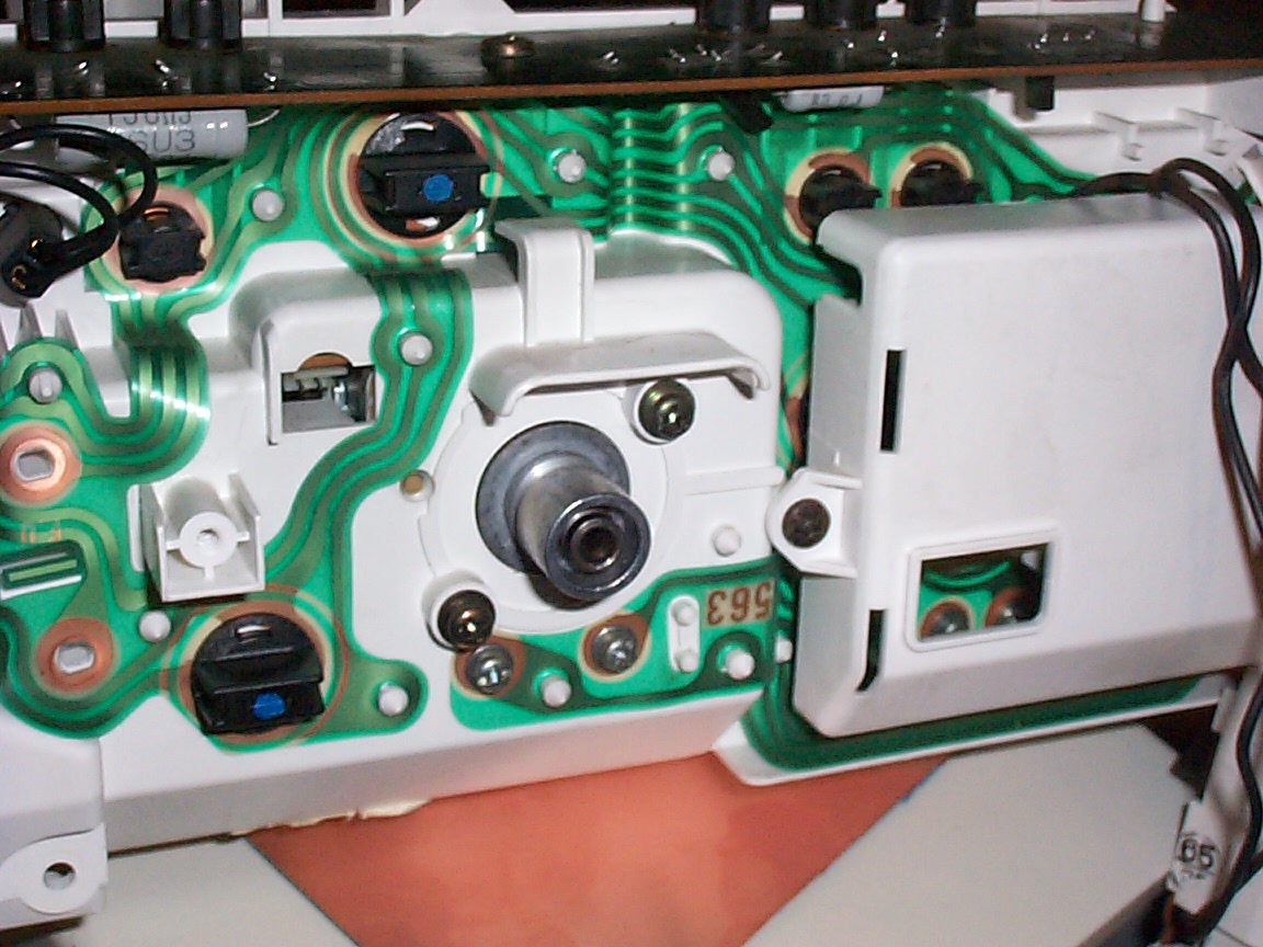
here is the back of the dashboard - note the empty VSS-amp housing on the left - this will be populated with the UI driver board.
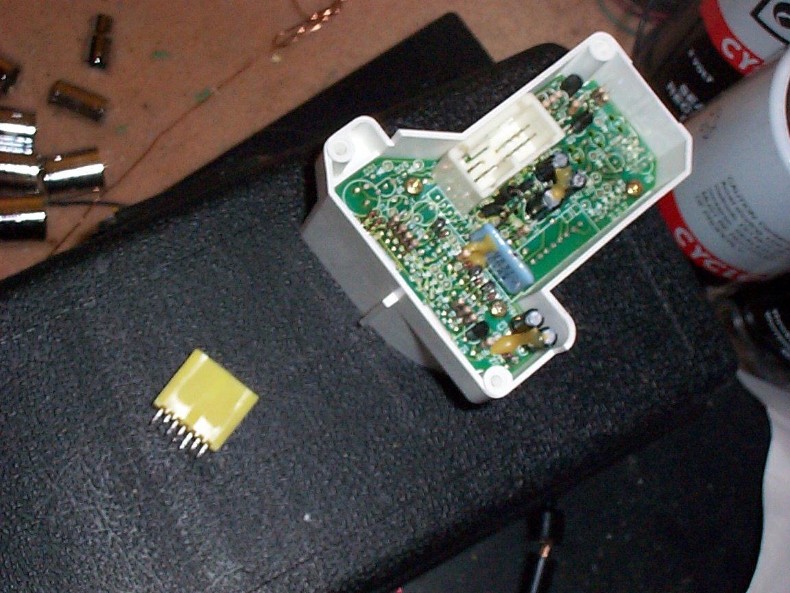
here is the desoldered connector from the UI board and the 'safety module' that will be replaced with a LCD panel.
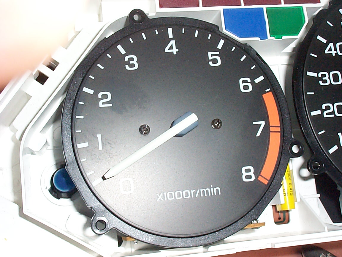
here is the tach - it will be interesting to see how I modify this to corrispond to the 10k redline of my motor. One possibility is just to drive it / 2 (so 5k RPM = 10k RPM) - but it may prove advisable to do something more creative, in order to keep the redline the same. Obviously the guage can easily be renumbered, and obviously calibration is no problem.
here is half of the dash hooked back in
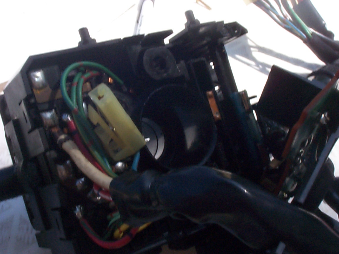
Third, it had a bad O2 sensor. Obviously, this didn't matter that much to me. And forth, and most annoying, a defect in the windsheild wiper switch would make it turn on and off seemingly at random. Apparently, somehow all the return springs got lost.
No one in socal sells combo switches. The honda dealer couldn't confirm availability, but thought he could get one in "a month or so". H-auto didn't have them in stock, which astounded me..
So fine - I can't buy one. Well, I don't want to drive around with a battery in my steering column to hold the wiper switch up for all of eternity, what can I do?
a bad picture of the problem assembly.
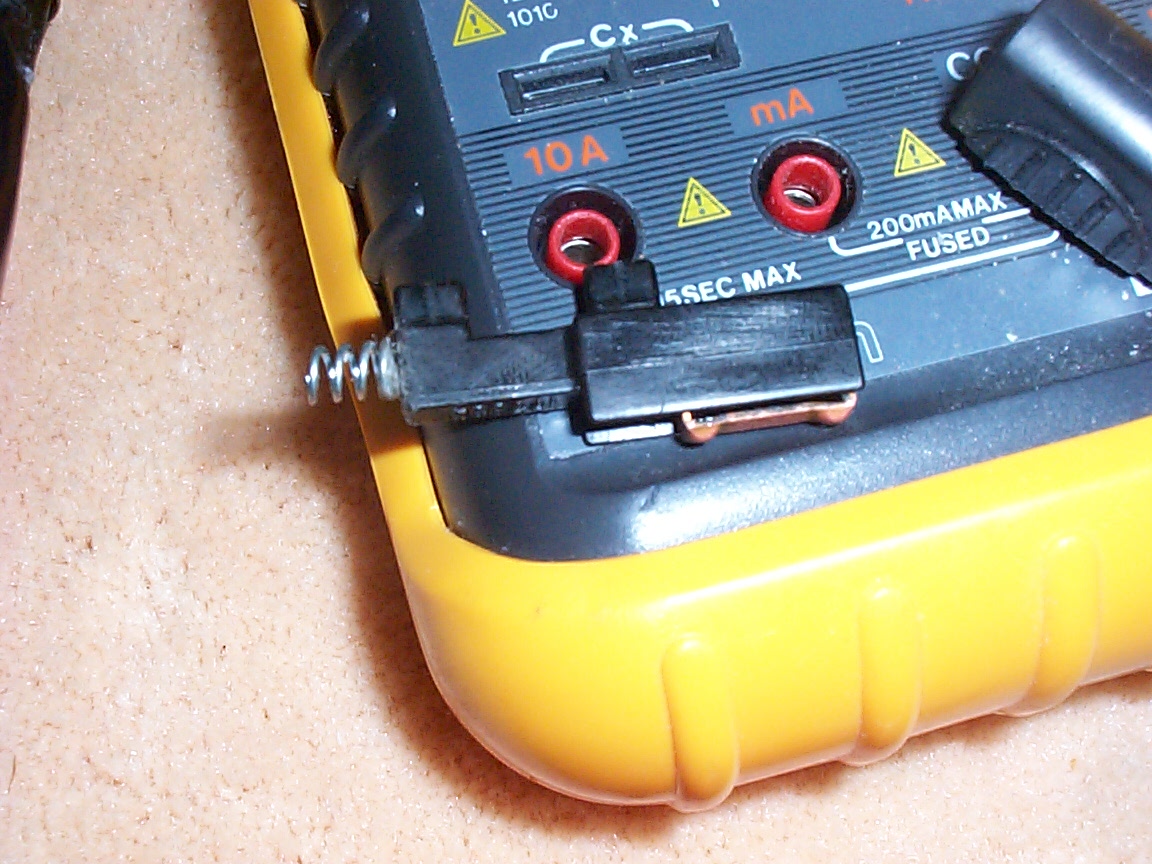
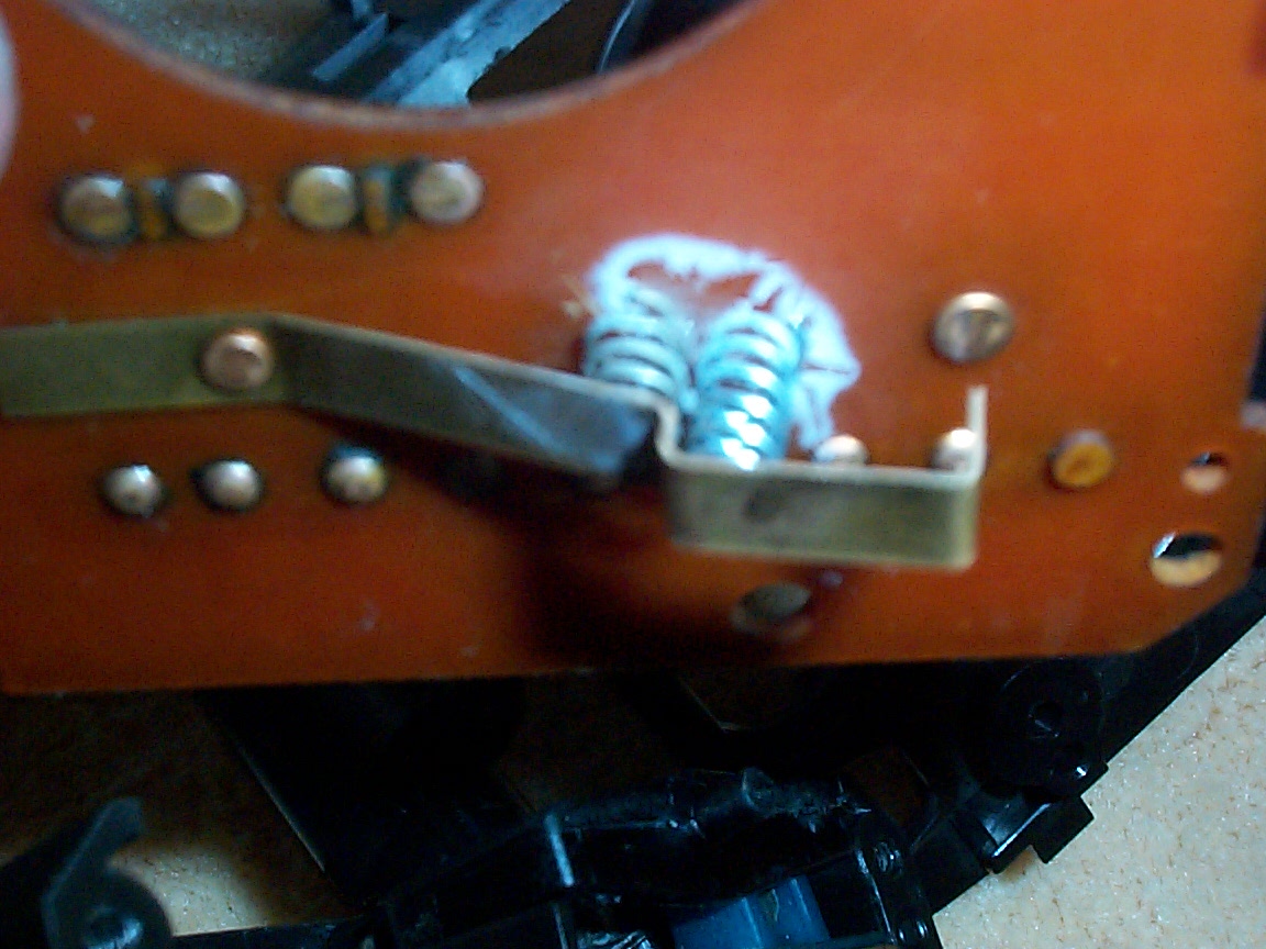
superglue and a 48 cent compression spring to the rescue
I have NO idea where the spring for the washer return was supposed to go. But this location seems to have worked okay..
Modifying the dash
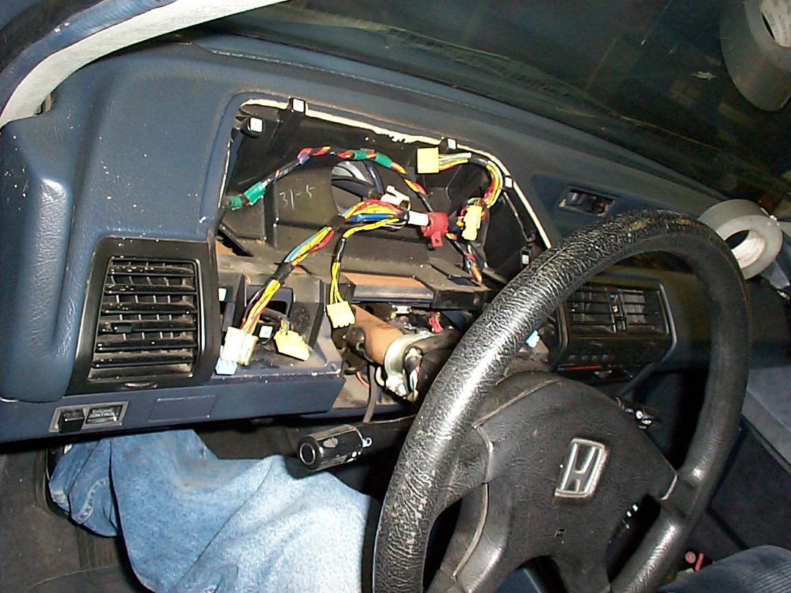
here is a high res pic of the dash dissasembled.Fixing the combo switch
My donor car had four blatent defects. First, it had a blown rear brake light bulb, causing the 'brake light fail' light to come on on the dash. Second, it had a misajusted door plate, causing the light in the car to flicker on and off. Both of these were easily fixed. Climate control and radiator (water cycles)
Mounting bracket for the heat/AC system, #1
Mounting bracket for heat/AC system, #2
Josh installing the heat/AC brackets
hrm something is a little out of true here
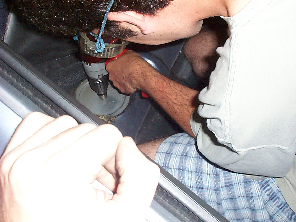
Josh drilling out the mount/support for the AC/heat brackets.
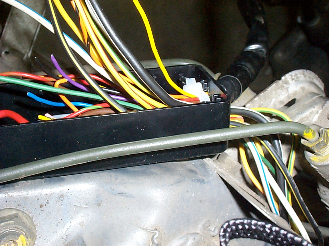
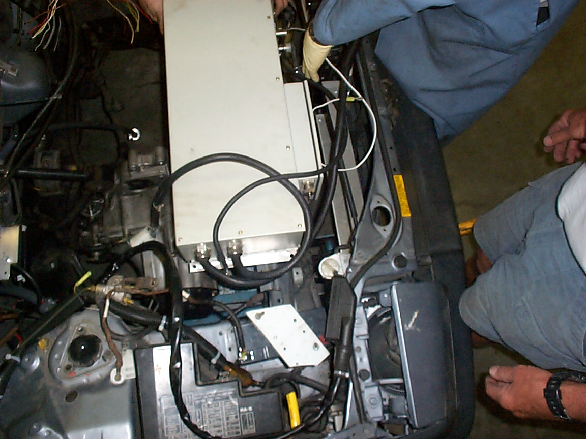
The master interface box which as you can see has a lot of wires, most of which haven't been hooked up yet
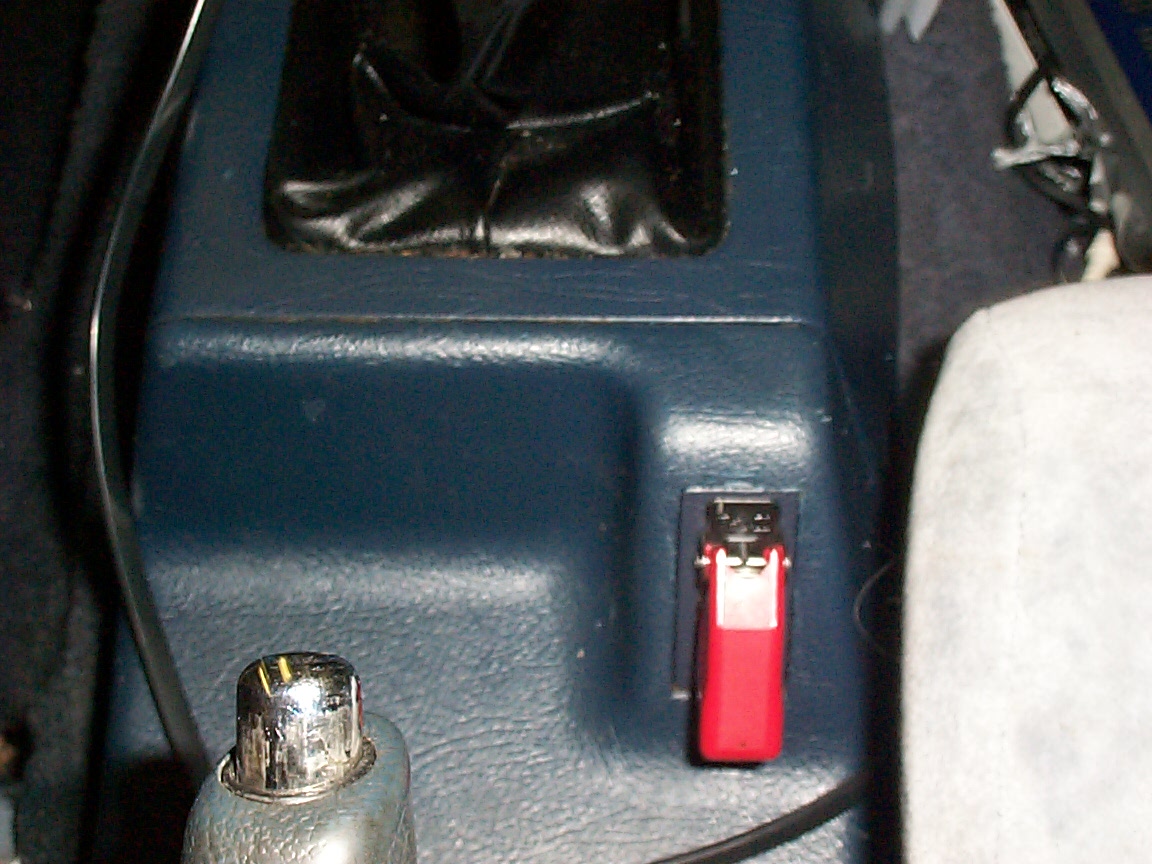
The EPO - lift cover and flip switch for emergancy power off.
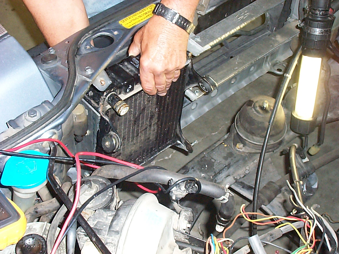
Leo fitting the radiator
Spin up test, part one
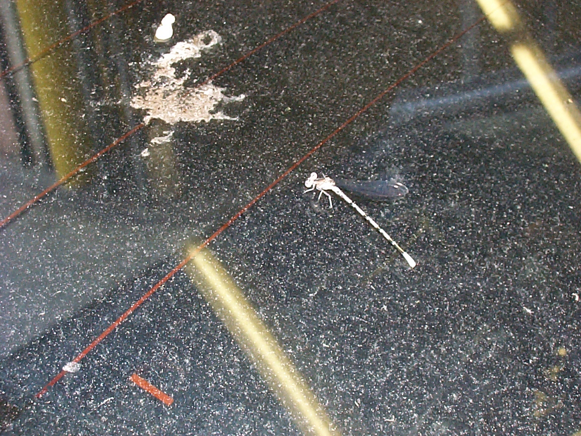
and we all fly away - dragon fly away. We rode a bubble through the sun - we all knew it could be done. There were men with firy wings - and a million burning things..
DO NOT DO THIS!. Note the red alligator clip to the frame of the inverter - this is bad. While in our case no damage was done, this is NOT a good idea.
the inverter lighting up dash indicators.
the interface box connecting everything togeather.
the radiator, all set to radiate.
The throttle position sender, all set to send throttle position information.
The evaporator lines all sawed off and ready to be mated to the peltier array
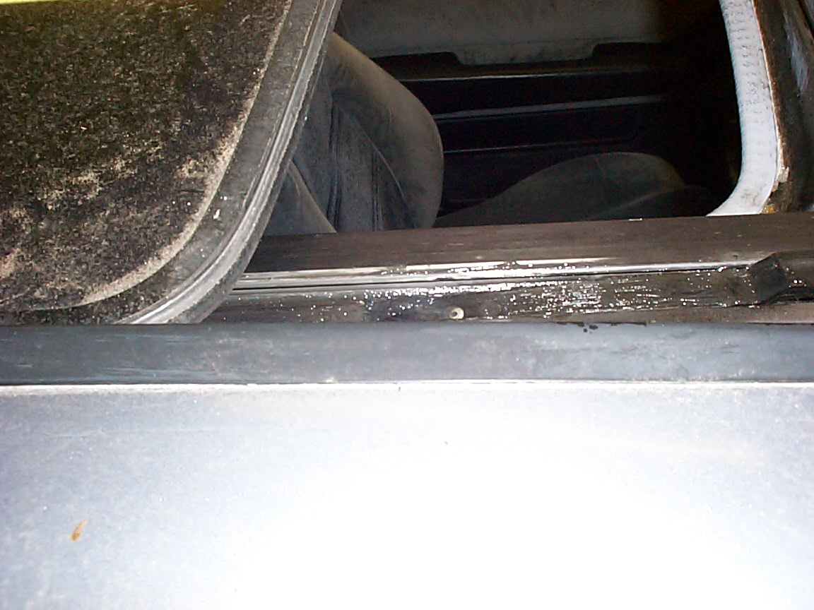
The sunroof, newly greased and sliding in and out quite nicely now.
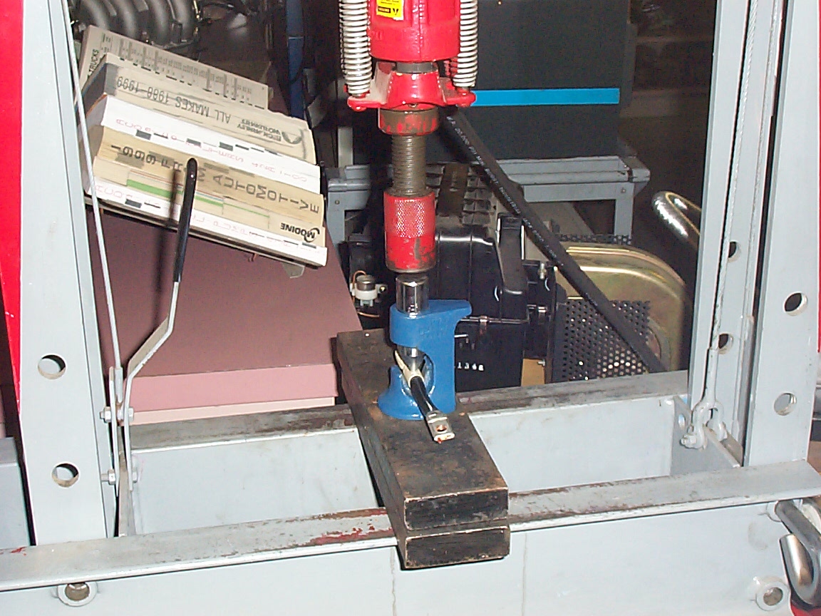
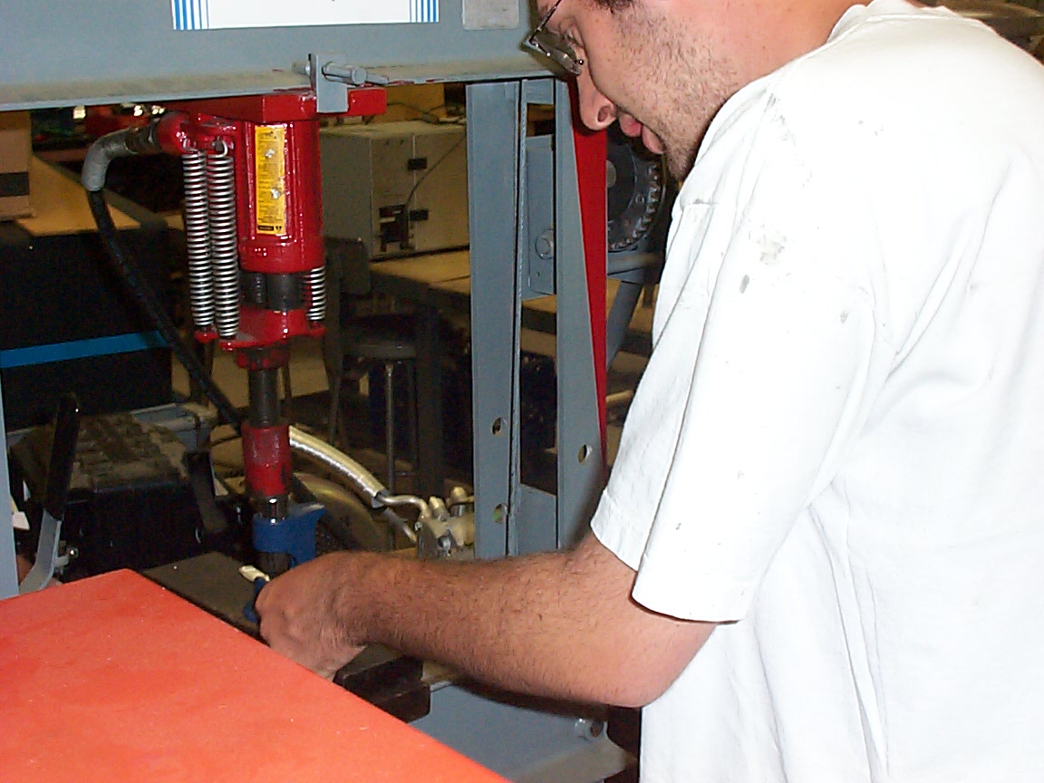
Using a press to crimp the Anderson connectors
Using a press to crimp the Anderson connectors, part two
Testing the inverter <-> car interface. Yep, it works. Press down the gas and the motor spins. Yippee.
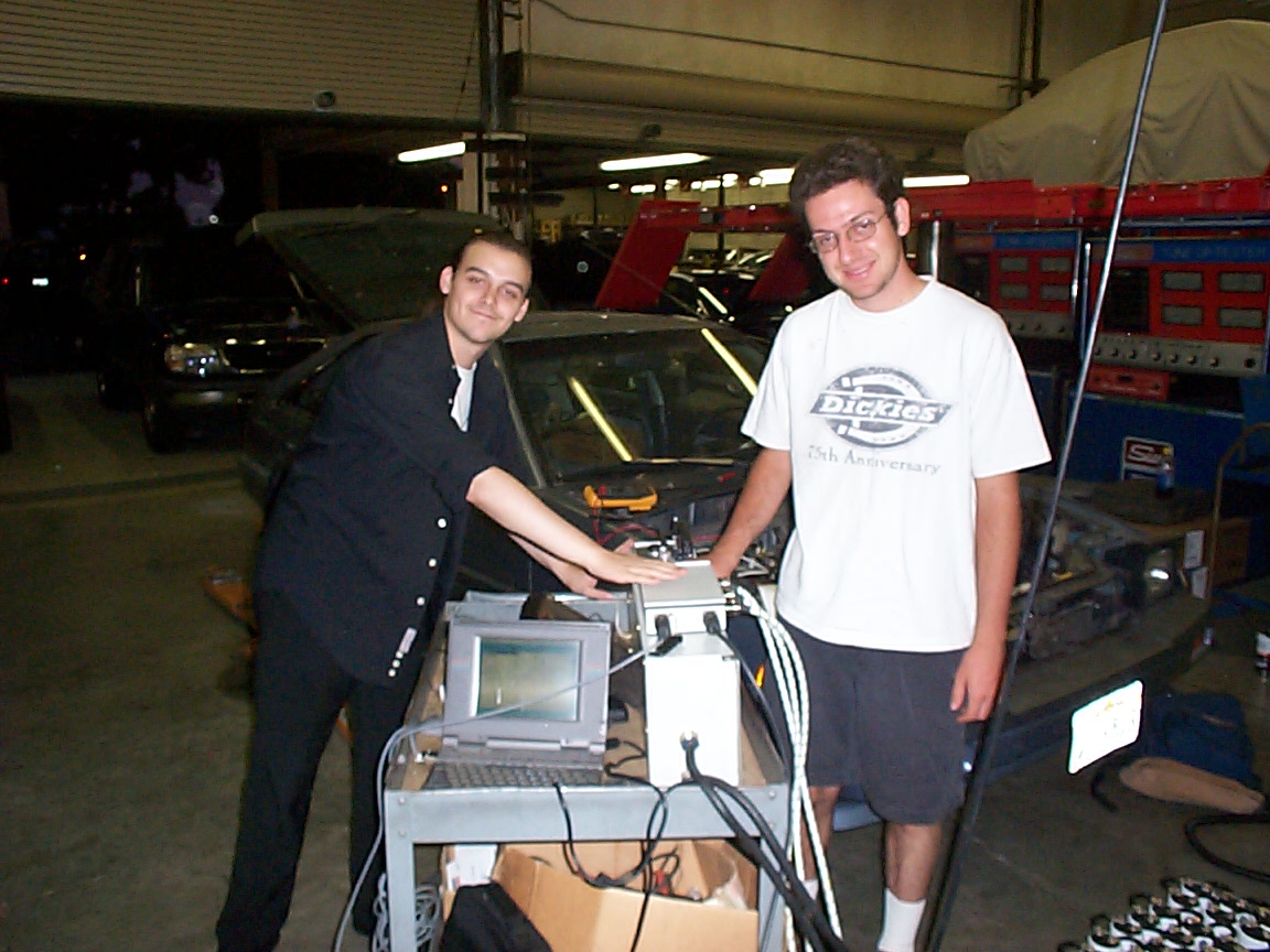
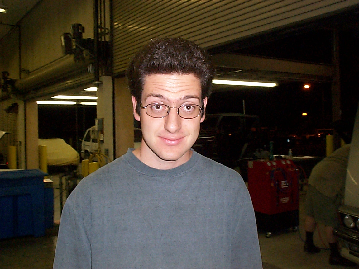
The wonder boys - That's Chris Mish on the left, and Josh Myers on the right. Josh is the mechanical guru, Chris the cynical 'it'll never work' voice of reason. Not shown are Leo and Prof MacFarland, providers of wisdom, historical detail, and Loren Wagner, our research assistant (mostly because we never see her).
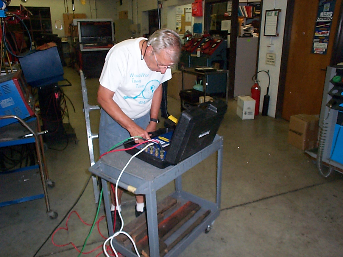
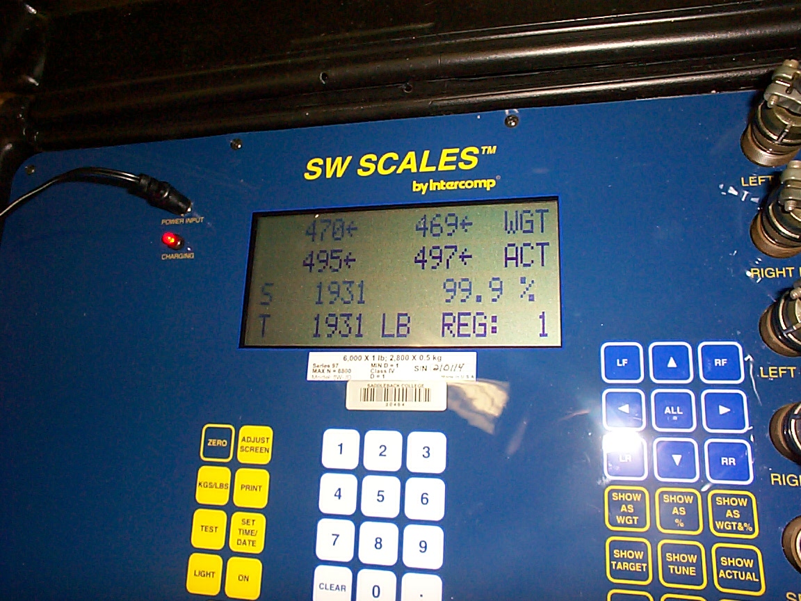
Leo at the controls of the scale.
the scale and what it has to say about the car
lousy picture and if I had any common sense i'd delete it.
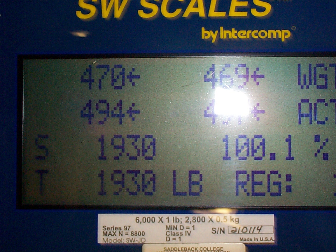
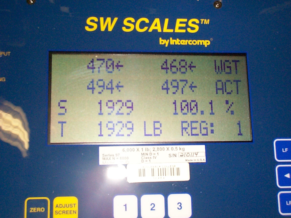
extreme close up of the scale display
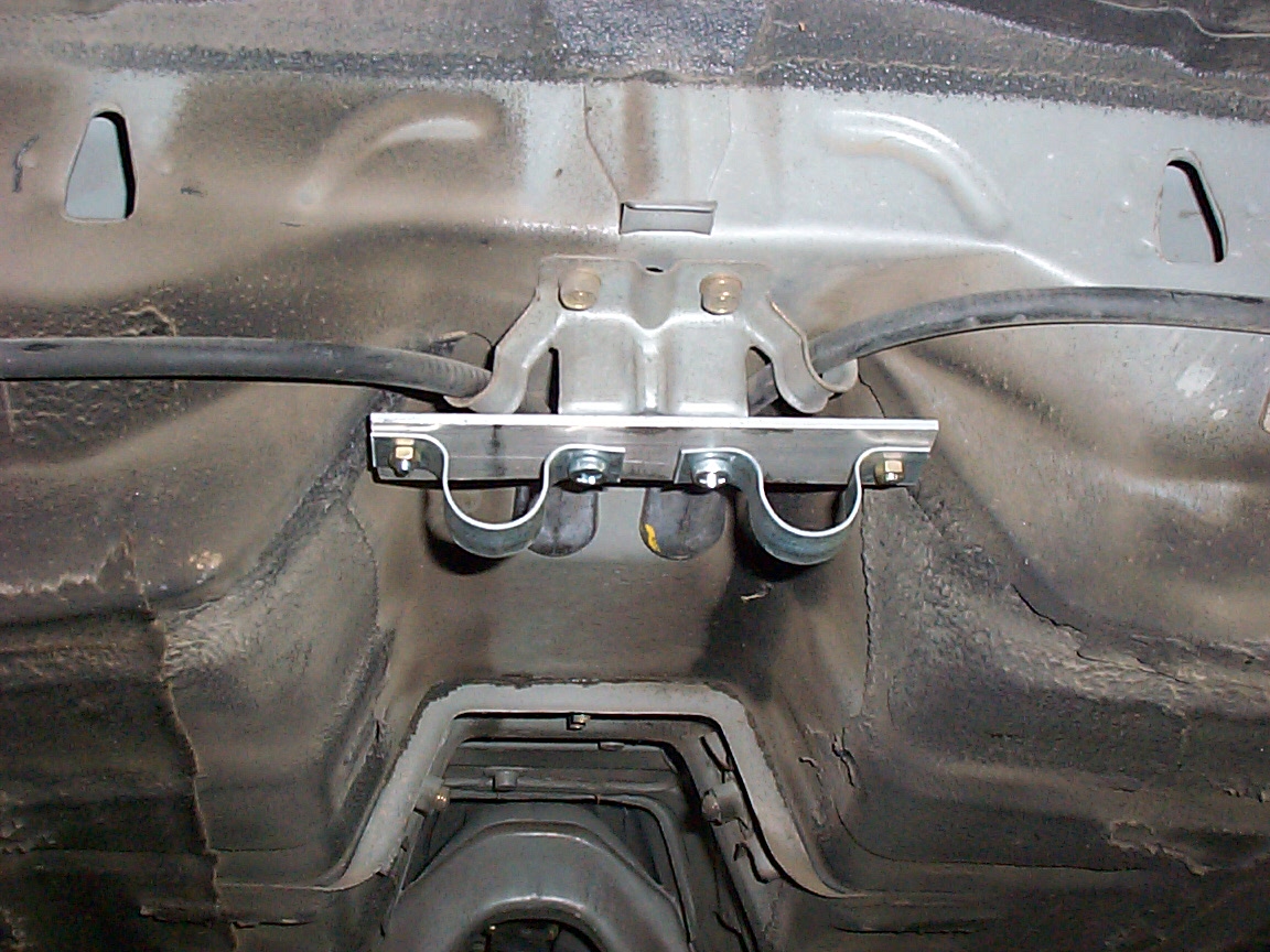
the back bracket all set to have conduit run through it.
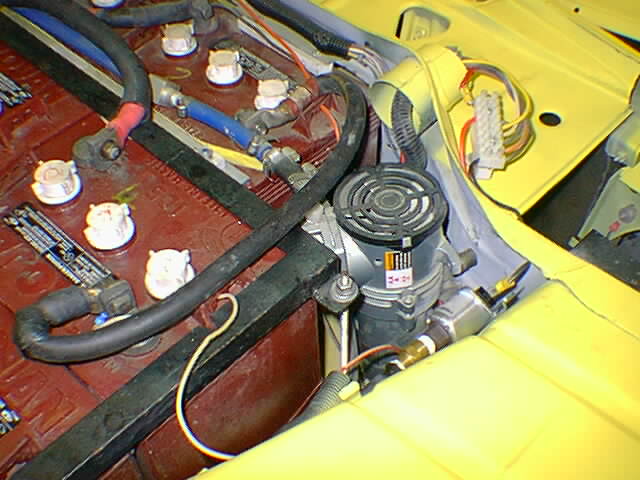
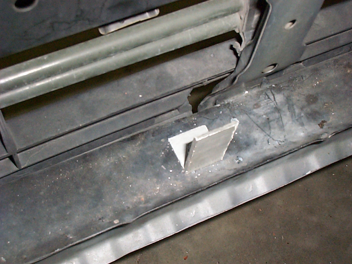
Ah, the places you can hide things The water pump will go in here, I hope
Anyone know what this is? I found it hiding in under the right corner of the car.
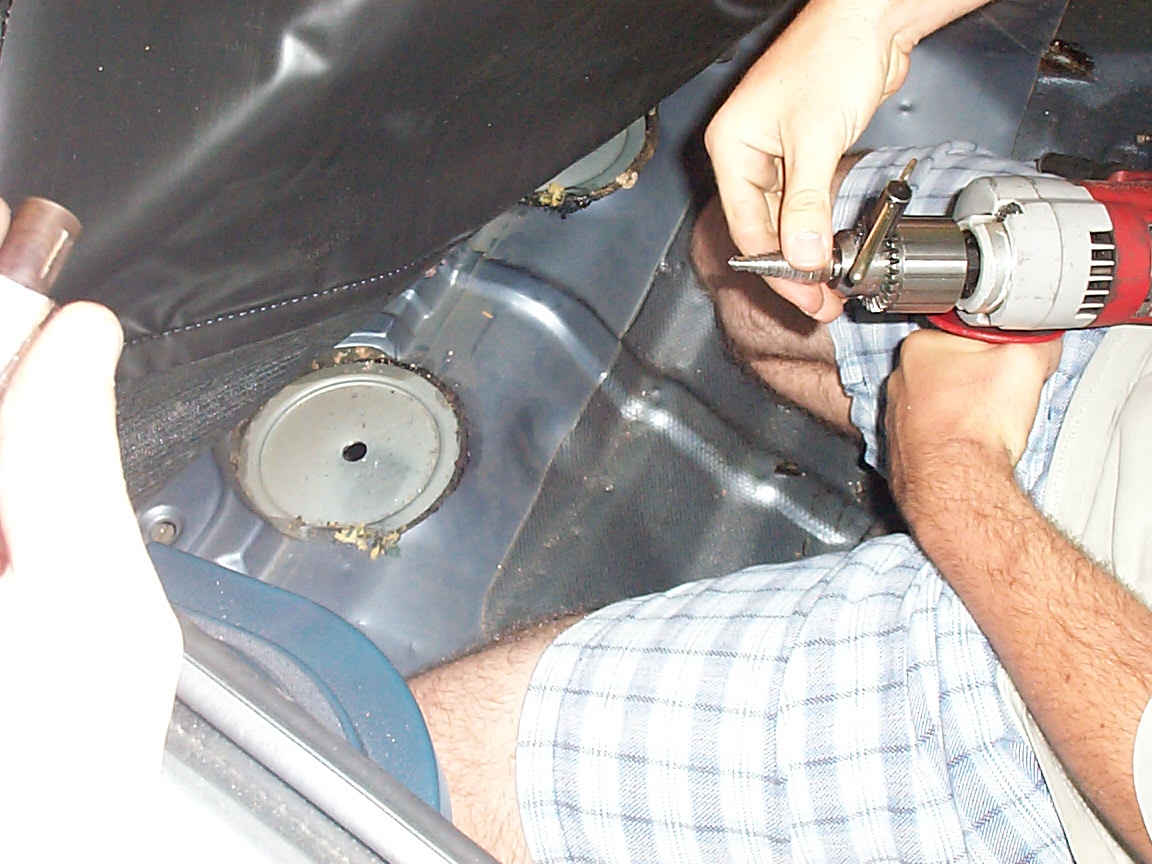
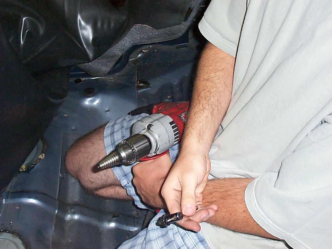
Josh prepares to drill a hole to pass the conduit into the cabin
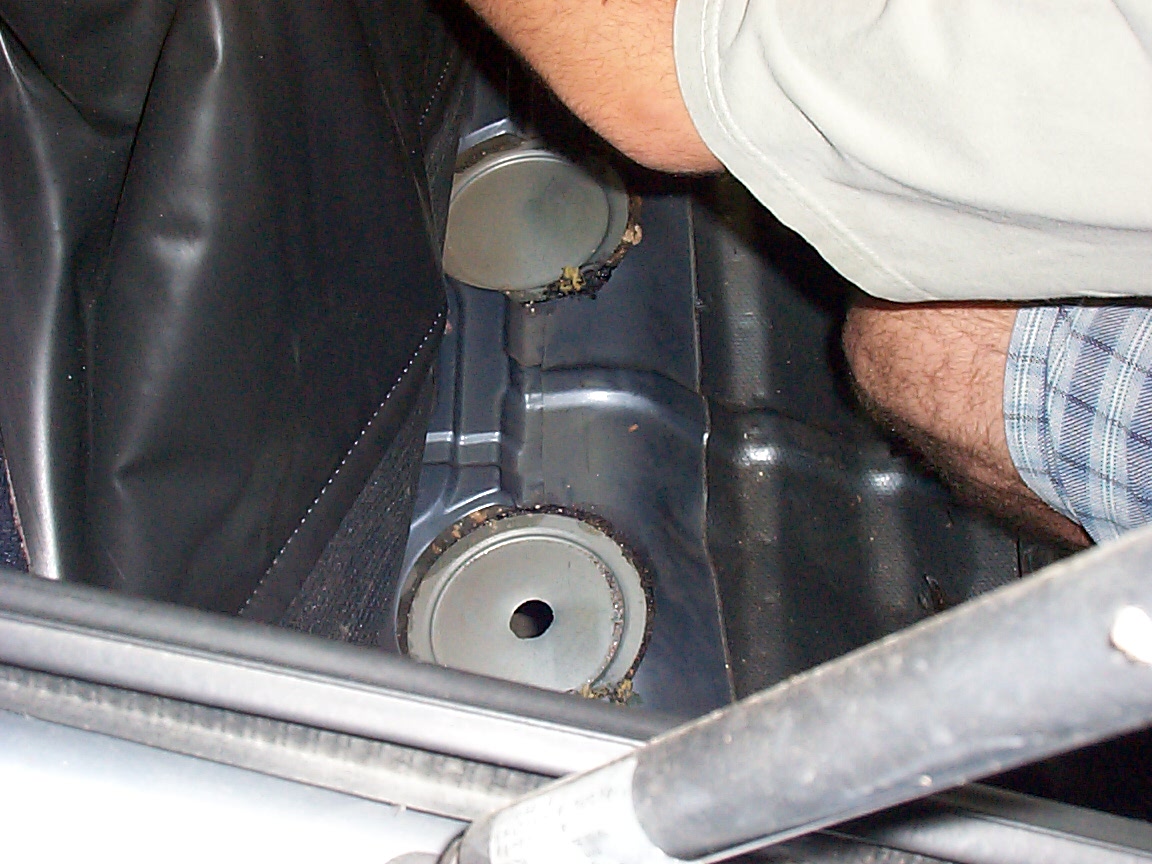
The hole but it's too small.
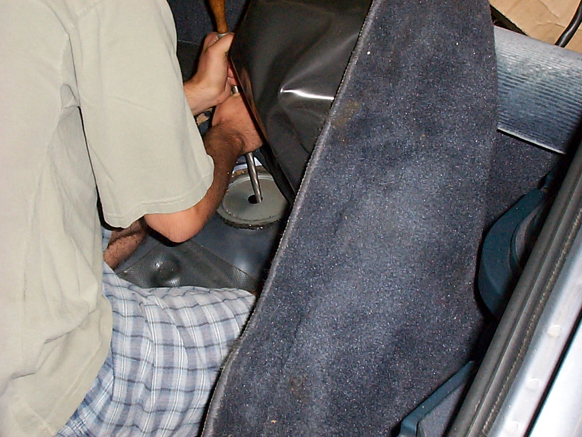
testing to see if the conduit fits
installing a run of the conduit to test the length
yep, it goes in the hole just fine
Click here for a whole page about the first attempt at a adapter plate.
Testing for a fit on the inverter
Testing for a fit on the CV joints
Testing for a fit ont he CV joints, continued
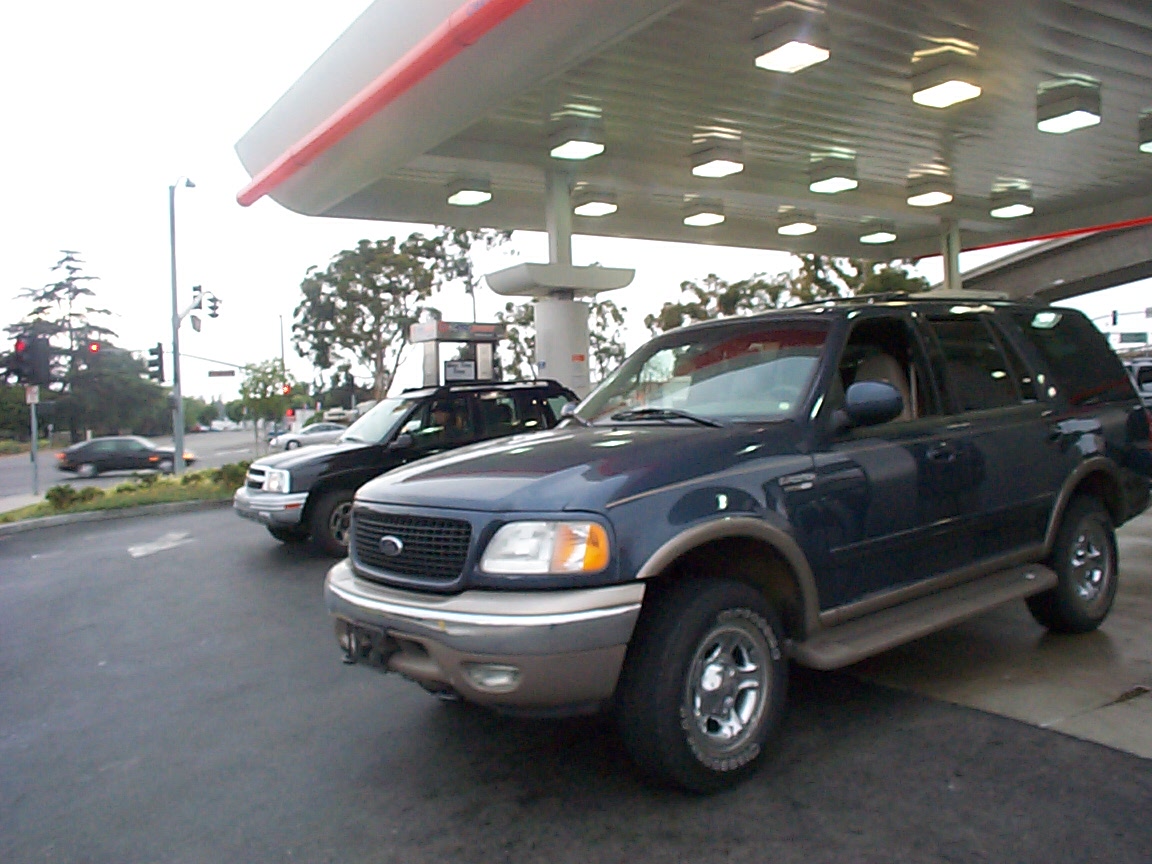
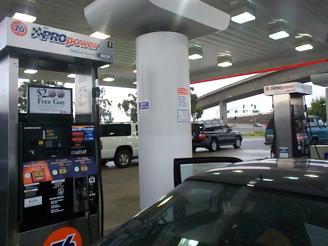
these people just don't get the law of supsupply and demand. You waste a bunch of gas, and consume more, the price is going to go up
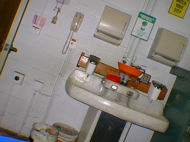
this is a test shot. (although, you can see the nifty eyewash station)
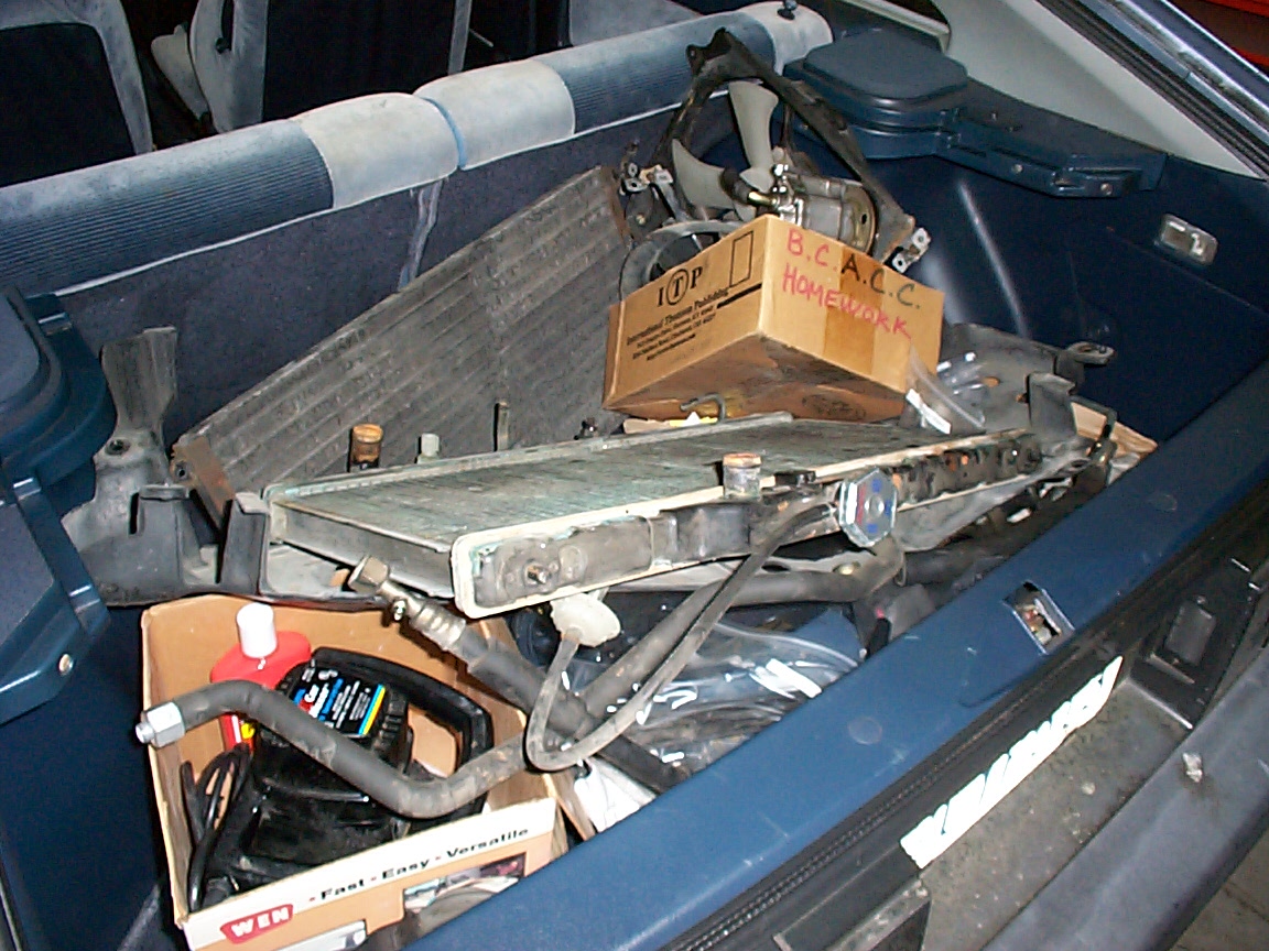
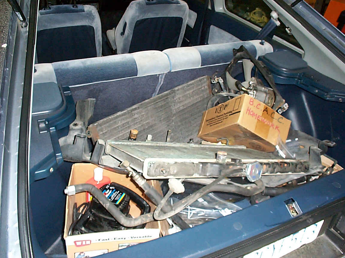
this is a high res pic of all the parts stuffed back into the car so it could be rolled back out. Wow, there's a lot of junk in there.
this is a high res pic of all the junk in the trunk right now.. radiater fans, condensors, radiators, etc
this is a high res pic of all the junk in the trunk right now.. radiater fans, condensors, radiators, etc - another angle
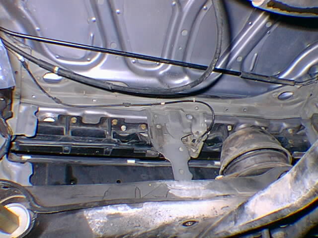
this is a look under the hood, from a very unusual angle.
this is another unusual angle shot
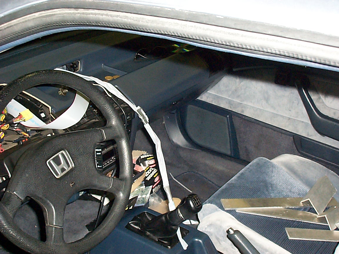
this is a picture of the somewhat trashed interior of the car
test pic to see if the cam still works after being dropped. Yep.
grass is always greener.
From bottom to top, Nicka, Phoebe, Me
Adapter Plate pictures
Wedging the stuff in, part duex
Random and junk pictures